HxC SD: Mounting a tiny LCD and slimming it down

Hey my friends.

Since a really long time (long before HxC Rev.F and Slim Edition), I wanted to take my Rev.C HxC SD Floppy emulator and slim it down as much as possible in order to make it moddable for my taste :)
The one thing I didn't like much was the big (lol) LCD screen that occupied a lot of space.

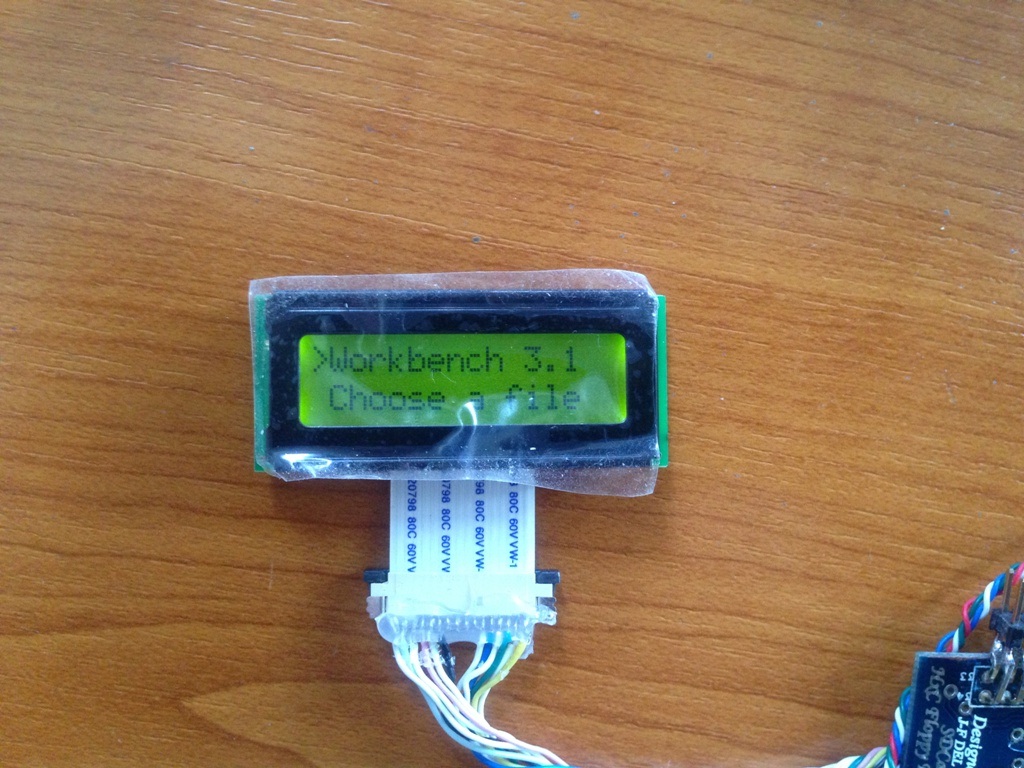
While searching the bay, I managed to get a really Tiny 16x2 LCD Screen that was really nice for my needs but instead of having pins, it had a ribbon as it's meant for embedded projects.

I don't mind though, as I also got a connector to wire it.
As you can see from the picture below... the size difference is definitely noticeable compared with the default 16x2 LCD screen of HxC SD :)

In order to use this LCD screen, I needed to short 2 of the opened jumper locations as I saw from the online   datasheet.

After carefully wiring the connector for the ribbon... SUCCESS I had :)

As I said before, I wanted to slim the HxC SD down so I decided to unsolder the PIC and IC sockets in order to gain some height space. It was a really boring procedure but nothing one man can't do with a bit o patience :)
Since I'm not the best in unsoldering with the El'Cheapo desoldering pump that I own, I managed to loose connection from 3 lines, which after a continuity test, managed to find from nearby lines so no problem at that! (Thank God to my 1st Rev.B to Rev.C HxC SD which helped me find the missing tracks.)
After unsoldering the LCD Header (after my successfull experiment) I soldered the wires from the tiny LCD connector directly to HxC and also hotglued a tiny pcb juts to hold the wires together not to get cut.
I also unsoldered the Drive selection jumpers and short the pins where a jumper for assigne DF0 would have been :)

You can see here the cable connection and the unsoldered PIC and IC :)

Ok, I was happy with the result, but more stuff needed to get out of the way to gain some height space as well. Obstacles were:

  • The 34pin floppy connector
  • The mini buzzer
  • The LCD contrast trimmer
  • The 3x PCB mounted buttons
  • The molex floppy power connector
Ok lets get these things one by one shall we?
The 34pin floppy connector
First of all I removed the plastic rectangle that surrounds the pins as I didn't care :)
then I bent all the pins with pliers 90 degrees. Bending one-by-one was such a BORING procedure that required a bit of attention but had to be done :(
Once might ask... WHY haven't you desoldered the header and solder an angled dual row pin connector instead? Well... firstly because I was afraid of doing some damage with desoldering, but most important that I saw that the angled double row pins had more height that I wanted.
Anyway... after bending the pins, I soldered a dual row of pins to the bent pins and everything was nice and firm :)
The mini buzzer
The buzzer is rather small, but still it has some height I didn't like. I decided to unsolder it and attach it via hotglue to the back of the unit in the middle between the lower and upper part of the PCB :) That made it a lot lower than before.
The LCD contrast trimmer
That bugger has some great height due to big leg pins. I desolder teh bastard quickly and as I measured it, there was no need to reattach it elsewhere, so I just soldered a fixed resistor value that worked great with my LCD as there was no way of putting another screen than the one I currently own.
The 3x PCB mounted buttons.
Despite being ok, the position of these 2 buttons didn't suit my needs not to mention their height was out of the question as well, so they had to go. I unsoldered these as well, and rewired them to an external mini PCB that I can put whenever I want.
The molex floppy power connector
This was too easy. I just use pliers to remove the plastic insulation of the connector alas I got some exposed pins that I will use in the future with a flat female connector :)
After all this work I tested everything but the LCD screen didn't show much stuff :O WTF. I was really sad.
AFTER a long time testing to see what I did wrong, I found that one pin of the LCD screen wasn't making a firm connection with one of the PIC pins so I just wired a bridge underneath and everything was fine as well :) I so, unglued the mini pcb and resoldered the wires once again, hotgluing them directly to the PCB and now everything worked as it should without issues!
Here you can see some pics of the whole custom work.

Just as a comparison with the original unit, I'll present some photos from my 1st Rev.B to Rev.C HxC SD. Don't take in mind the custom PCB with the RAM module that converts the board from Rev.B to Rev.C just see the whole PCB and compare :)

Not bad aye? Just tested it by:
  • Playing Hybris using Kickstart 1.3 + Disabled ACA
  • Loading WB using Kickstart 3.1 + Enabled ACA
No problem so far.
Good to know I have a modded HxC SD for future mods... :)
Stay tuned