Reverse engineering the LCD interface
So I was having trouble getting the LCD working initially, so I ended up probing a working HDMI to LCD converter board sold by adafruit. You see, this board was driving my LCD just fine, but my FPGA couldn’t do diddly. So I wanted to see what I was missing.
This proved more difficult because of these 40-pin FPC connectors. Not sure what the pitch is, but it’s really freakin’ close together.
With a lighted magnifier (3x diopter?), and sharp o’scope probe, I was able to isolate individual pins on the 40-pin, long enough to hit the stop button on the scope.
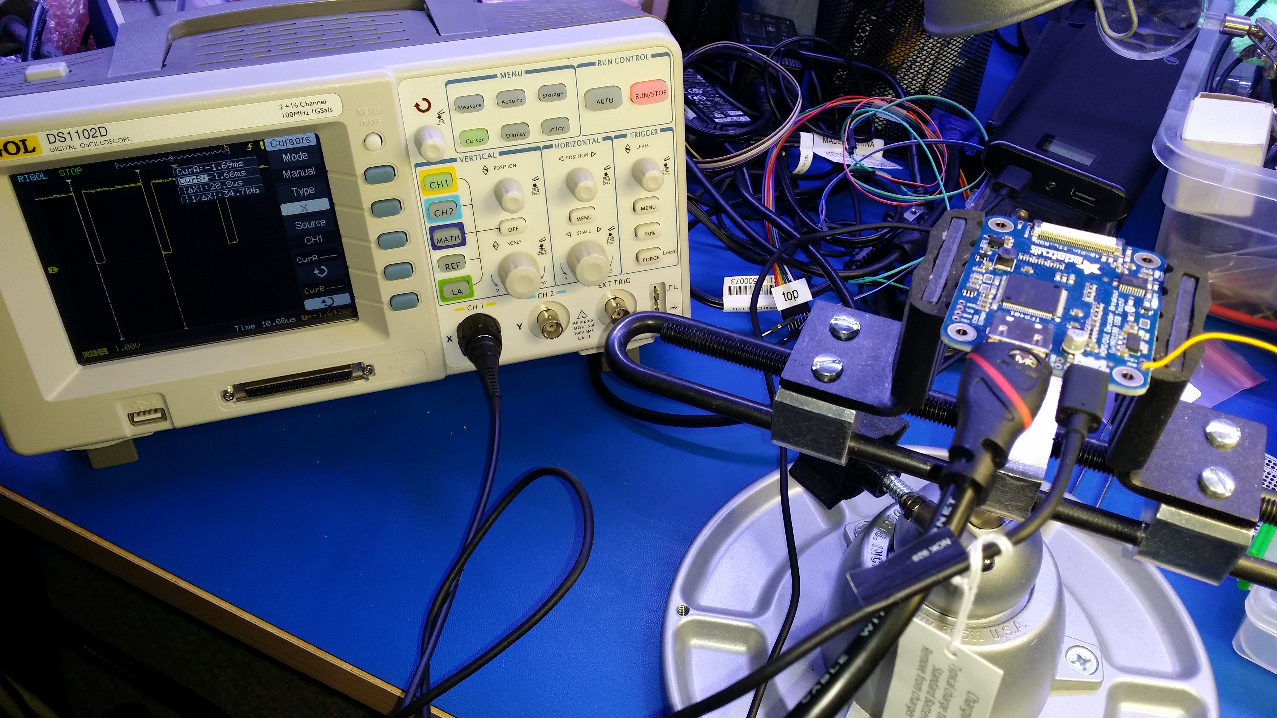
What you see on the screen is (likely) the probing of the HSYNC pin, showing the pulse in between each line. So between pulses, you’d have 800 pixels worth of video data.
I’ll post the LCD and associated required timing specs once I get everything working 100%, but I’m over the hurdles.