Building the Amiga 4000 Replica – Part 1
In my series of building different Amiga replicas, it is time for the Amiga 4000.
First of all, locator is available at: http://locator.reamiga.info/locator.php?project=A4000
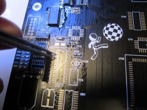
Populate all passives (resistors, Capacitors, Resistornets, Transistors and diodes) but skip the electrolytic caps.
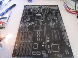
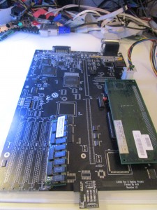
you should have a board like:
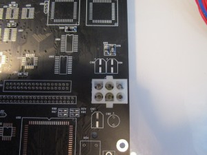
First solder in the powerconnector:
Make sure you have the orientation correct.
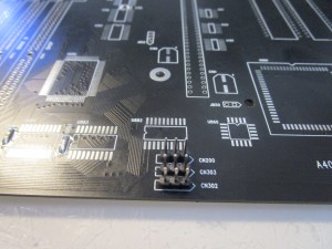
and solder in the headers for the leds (and disable key as. why not)
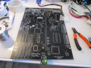
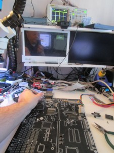
now if you poweron. you should get powerled light. shown here with my small testboard:
ok 5V seems to work anyway. thats good. lets start doing some real stuff.
First of all, lets get the reset working:
add U141 (7407), U140 (74F32) and U130 (74F08)
Now time to add more.
Add ALICE, LISA, GARY, U154 (28.xxMHz), U975, U976 (74HCT166), U131 (7406), the fuse at F175 (the flat component close to CIAs), RGB Connector.
Now you should get a H and V Sync:
here you can see on my oscilloscope that I got a H sync. and my monitor gives a VGA splash screen. however not all monitors does this. some just get a little big lighter.
a note here TECHNICALLY U976 and U131 is not needed for this. but adding those will give a correct MDAT signal out from U975 so adding it here makes more sense. and if you forget the fuse. you will not get a H and V sync to monitor, but oscilloscope will measure it.
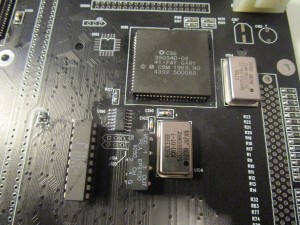
Time to fix some clockhandling:
add: U106 (74F74), U103 (This is usually socketed) (74FCT244 DIL), U102 (Delayline), U104 (50MHz Oscillator)
Next step_:
add Bridgette, ROM sockets (put in DiagROM), U901, CPU Slot, CPU Slot Jumpers (J104, J100), U350 (8520)
Set CPU slot jumpers after what your CPU board uses, 1-2 (INT) for 3630, 2-3(EXT) for 3640/3660
(if you put in a cpucard now you shold be able to measure databus/addressbusactivity on an oscilloscope)
however lets go on add more:
U354 (74HCT174), U311 (7407), U703 (74FCT646), U700 and U707 (74F245), U145 (74F521)
power on and you SHOULD get a powerled going bright after 1 second.
SOMETIMES this will need a forced reset, it is done by shorting those 2 pins on the RTC:
IF this is needed for you. you will need to do this everytime you test until a point (that I will tell later in the guide) this is due to floating signals etc and is fully normal. (took a while for me to figure out that the reset-thing was needed)
Anyway, add Paula, U304 (1488) and serial/par port.
Diagrom will not output serialdata (weirdly enough. didn’t take a photo at this stage, will add later)
(remember the resetthing!)
now lets add more:
U213, U212 (GALs), U216 (74F841), Chipmemsocket.
DiagROM should now detect Chipmem correct.
Here can you maybe see that I am using a 8MB simm, this is as 8MB simms are cheaper than 2MB simms, and works fine.
(NO!! you will not get 8MB chipmem, 6MB is just “wasted”) a 4MB simm would give you 1MB chip, as doublesided simms only give 2MB.
Ayway now it is a good time to add all jumpers: and here is a list of all with defaultsettings (PAL)
CN404 (CD Audio IN. NO jumper)
J500 Sync on green Default is apparently not connected.
J501 and J502, LISA and DAC syncs, default on both us 2-3
J212 PAL/NTSC Default is 2-3 (PAL)
J214 Just have this at 2-3 OK?
J213 (The Free sex and beer jumper) Set to 1-2 NO YOU CANNOT GET 8MB CHIP! there was no 8MB LISA.
J852 SIMM SIZE. Set to 1-2 (to get max 16MB, 2-3 is max 4MB of RAM)
J850 do not even bother to populate unless you have a Amiga 3400 020/030 cpucard all the extra GALs needed etc)
J100/J102 CPU Clock jumpers. depends on your card 1-2 is INT 2-3 is EXT. for 3630 set to INT, 3640 EXT. CSMK2 INT etc. read manul of CPU Card.
J151 ROMSPEED 1-2 is 200ns and 2-3 is 160, default is 1-2
J352 DF0: Select. 1-2 is INT, 2-3 is EXT. Default is 1-2
J351 DF1=880K, Put a jumper here if df1 is a DD drive. default is not connected.
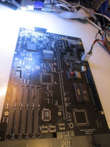
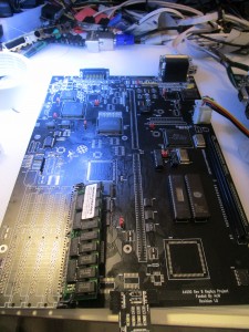
Anyway this is your board now:
And this is where I leave you for this part! next part we do the rest!
