Commodore Amiga AutoConfig expansion card process
Since I’ve been reverse engineering a DataFlyer Plus HDD SCSI expansion card for the Commodore Amiga, I’ve needed to get a much better understanding of how the AutoConfig process works. I’m by far no expert on it, but I have learned a lot and wanted to share a couple logic analyzer traces of this occurring in the wild. The Commodore documentation refers to these expansion cards as PICs or Plug-in Cards.
Before we talk about the autoconfig process, it might helpful to know the make up of a “base” expansion card, in terms of hardware. I describe with PCB photos and some part numbers here, but the key parts are:
- Some resistor network packs that describe $E8 0000, the default autoconfig address.
- An 8-bit latch like the 74LS373, which grabs the relocated address from the Amiga data bus once the base address write occurs.
- An 8-bit comparator like the 74LS521N, which compares the top 8-bits of the Amiga Address bus, so A23-A16, for a match to either the default $E8 or the new $E9, etc.
- A ROM like a 27C128 or 27C256 that contains the configuration information, boot code, etc.
Zorro II bus autoconfig process:
- It’s important to first realize two things:
- This information transfer is done in NIBBLES, so 4-bits at a time, and placed on the Amiga databus D15-D12. This also explains why on the Dataflyer, only the top 4 bits of the ROM data pins are connected.
- Much(but not all!!) of the configuration information is INVERTED and so if you’re looking at these structures and can’t find them, that’s why.
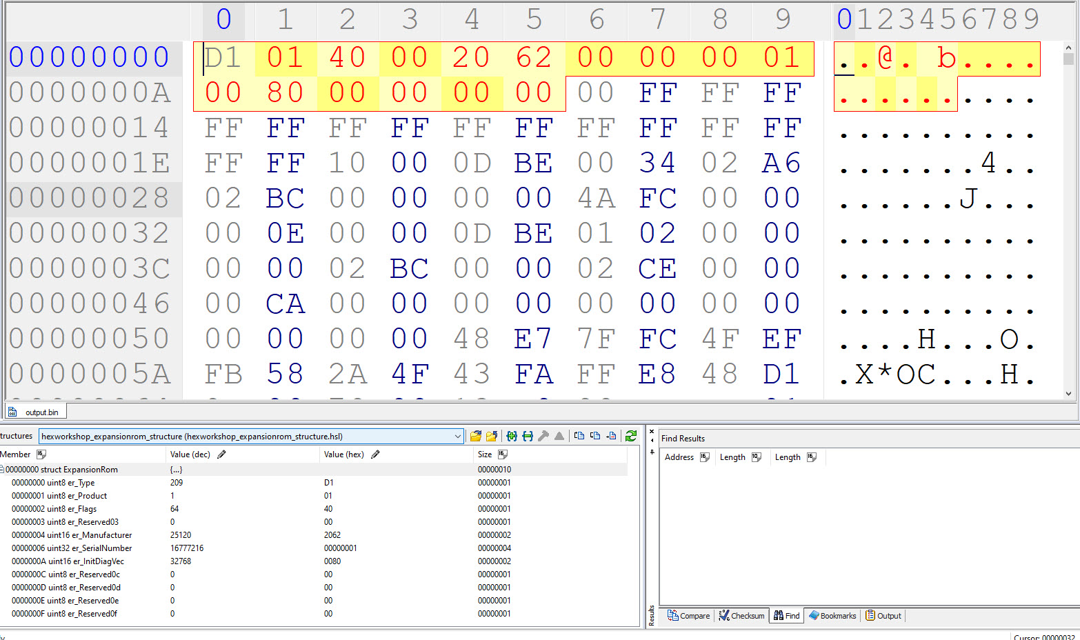
- The Amiga starts sending read requests on 0xE8 0000. It’s looking for an Expansion ROM structure. This contains information like the manufacturer id, product id, serial number, and so forth. This information is typically stored in the ROM at the top addresses. You can see this decoded on the Dataflyer ROM file:
- There are other structures included as well that I won’t dive into here. I do plan on recording the full rom read once I get an appropriate logic analyzer test clip. I can dive into those things later.
- Once the Amiga has the configuration size, which appears to be commonly $010000, then it can relocate the card from the default $E8 0000 to a new space. That space is normally $E9 0000 with one card, $EA 0000 for two cards, and so on.
- The way the Amiga communicates the new address to the card is with a write to the original address range, specifically $E8 0024. This is written to the top byte of the Amiga databus at D15-D8.
- The dataflyer card, as I’d imagine many cards do, uses a PAL to recognize this write, and sends a latch enable signal to the 373 to tell it grab this new address. I have two images below showing both the original PAL responding, and my new GAL recreation. Notice how similar they are! See the yellow line.
- Then, once the latch has the new address, we have to tell the comparator to start listening to the new address, so the PAL then asserts the 373’s Output Enable(OE). This OE signal is also connected to the Amiga’s card edge pin 11. This tells the Amiga “hey, I got it”, but could also be used in the case of the A2000, to let another card that their turn is up to start the autoconfig process for them.
- Once that OE signal is asserted, that card should stop responding on $E8 0000 and start listening to their newly assigned address.
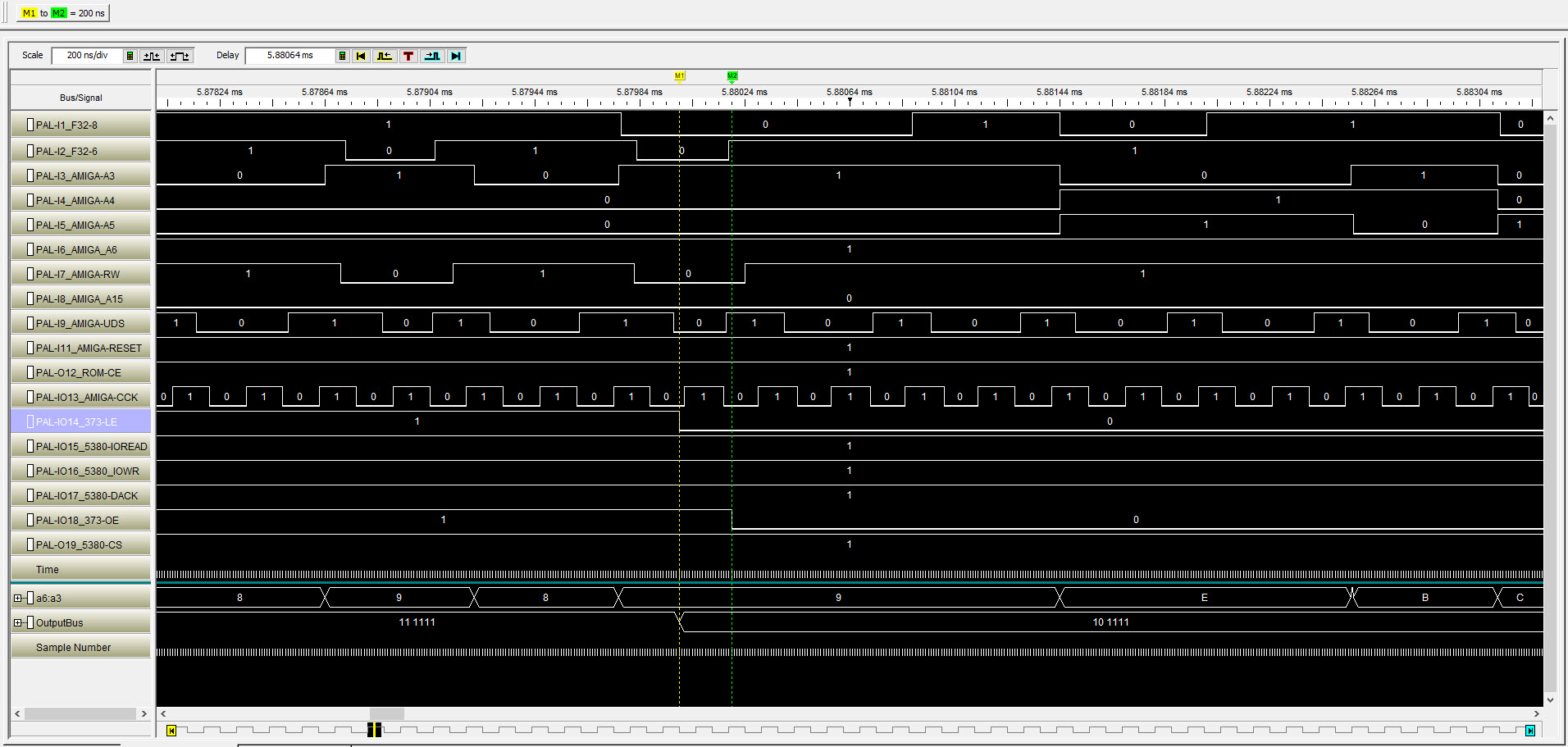
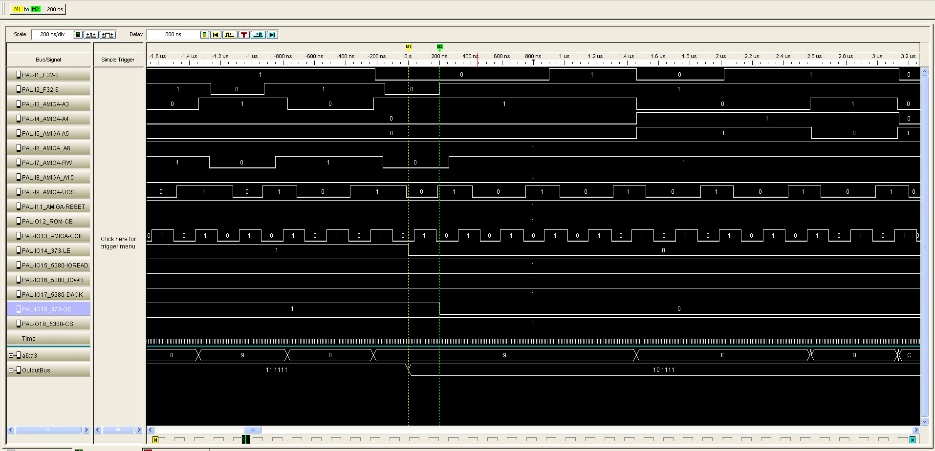
These logic analyzer traces are read left to right, and contain 10ns samples of the various signals listed from top to bottom. The various PAL pins are listed, and you can see I9-I11, the straight input pins, the O pins (12 and 19) which are fixed output, and then IO pins which can be either. The PAL uses boolean algebra logic equations to control the output pins based on the input pins.
I’ve been reversing the BUSS PAL, which is the only PAL required on the DataFlyer SCSI version. The IDE version requires both the BUSS PAL, but also a DTACK02 PAL, which I will likely start reversing soon. I will be publishing the wincupl PLD files, plus the .jed files, once I’ve confirmed that they are valid. I have a prototype that is working perfectly in my environments.
References:
- https://wiki.amigaos.net/wiki/Expansion_Library
- Amiga Hardware Reference Manual. Page 431.
- https://en.wikipedia.org/wiki/Autoconfig
- Commodore Amiga 500/2000 Technical Reference Manual. Section 3.1 Designing Hardware for the Amiga Expansion Architecture. Page 17.