A600: Mounting HxC & Floppy Internally (Part 2)
Hey folks,
As I'm waiting for some stuff from eBay I couldn't just sit back and just do nothing :)
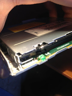
First of all, what I didn't like is the fact that the 26pin connector on the slim floppy drive doesn't have a MOTORLED signal as the Amiga drives but instead it has an onboard LED.
Since I wanted to have LED activity when the floppy was running, I just picked the LED signals at first just to have them for later usage.
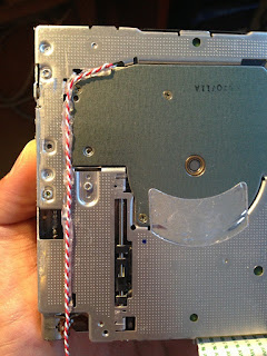
Sadly it's not so easy to capture the wires I soldered in the LED header inside but here we go...
Here you can see the back of the floppy drive where the thin 2 wires were hotglued to stay in place.
OK that was easy. I was trying to think where the LED could be used.
1st idea was to just wire it to the original Floppy LED so to illuminate both for the HxC and for the floppy drive. Despite being an ok solution, I didn't like it much as I wanted to know both floppy activities and not just one.
2nd idea was to mount another LED somewhere, but as you know, I don't want to ruin much the look by putting a LED just somewhere randomly.
While checking some pictures of the A600 from BBOAH I just zoomed one and performed a simply COPY-PASTE by selecting the floppy LED and putting it on the upper part.
That's how the concept picture looked after the MSPAINT copy-paste action (LOL)
Not bad at all since floppy area is larger than the Power and Hard Disk areas so it's not that bad.
The worst thing is that cutting it would be a major pain in the ass as you can see it has some curves that can't be made easily by hand...
Oh well... you know I don't give that up so easily when something comes in my mind :)
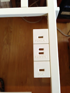
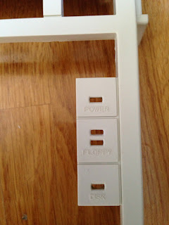
I can easily say that... THAT WAS THE TOUGHEST THING I have ever done by cutting an Amiga case by far. As mistakes can't be forgiven once you cut or drill, it took me A LOT OF TIME and patience in order to achieve the following...
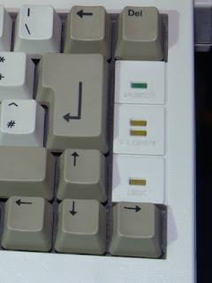
I think the results turned out really well. As you can see from the pictures I tried to recreate the original curves and I had success at a really good rate.
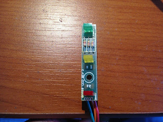
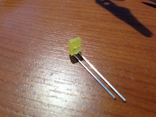
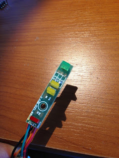
Ok next mod was to alter the mini PCB that helds the LEDS. I thought of changing all LEDS putting fresh ones, and also change a bit the coloring as following:
- Power --> GREEN
- Floppy Drive (slim) --> ORANGE
- HxC SD --> ORANGE
- Hard Disk --> RED
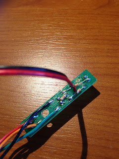
After removing the upper part of the resistors as they were on the way of the extra LED, I soldered them on the lower part after changing their position a bit (lol) and also I made 2 small holes in order for the cable to be able to reach the upper part where the extra LED would be mounted.
This is the upper part after the LED was mounted in the correct place. It took a while to align it by putting it temporarily on the case, then putting a drop of instant glue to secure it, and then remove it and solder it. Results were great :)
Putting a new LED gave me 2 extra wires that I had to mount to a connector. The default 4pin molex one, wasn't enough, so I desoldered it, and attached a 6pin female connector having all the required cables :)
Ofc, shrinking tube for extra protection was put along with a tie-wrap to secure the cables.
And we're ready to rock :D Not bad at all aye? I think it looks quite original.
I know that most of you don't like the idea of cutting the case. Well I don't like cutting it badly, but I think it's ok for a custom cut after all so I'm rather pleased.
Mini PCB with connector was ready but I had to put a connector inside as well. Since I didn't want to dismantle the whole mobo, I just added 2 pins (after applying a drop of instant glue and afterwards some hotglue to secure them in place.
Firing up the Amiga, gave me the classic Power and afterwars the Hard drive LED which is now Red instead of the default Orange. The colors are a lot nicer than the pictures and not so bright as they look :)
Testing the DF0 = HxC in the original header worked just fine :)
Testing now DF1 = slim floppy drive on the extra LED worked also fine \o/
And last but not least a photo of both the activity floppy LEDS working after I performed a diskcopy from HxC to Floppy drive :)
You can see that the Floppy drive is less bright than the rest of them. Probably because I left the onboard LED on the slim floppy which draws some current as well, so in the following days I will remove that as well :)
That's all for now...
Stay tuned for the next article in the following days (lets hope I'll receive the stuff from eBay soon) :)
EDIT:
After removing the internal slim floppy LED I realized that indeed the brightness improved a lot. I might change the resistor values in the future... but for now I'm good I think :)
