Upgrading the Apollo 1240 to 1260
Well next card in the series how to upgrade different 68040 cards to 68060, it is time for the Apollo 1240.
First, As Jens schönfeld ( Individual Computers ) owns the rights of the Apollo cards, I asked him for permissions especially when this requires a ROM change. he told me that I was allowed however only if I publish a diff..
But he also pointed out that he does not like the Apollo. This is no news but this is what he told me:
if you know how I feel about Apollos, you should also know that I do not encourage people to keep using them. They are instable by design – it’s inherent in the logic equations, and there is no way to improve the designs. They work to a certain degree (note that I specifically avoid the term “reliable”) if you have the right memory modules, but you can never get them to work totally reliable – no matter what speed and no matter what CPU.
Anyway, many thinks it still works and well it does run..
There is also a myth that the MACH chip must be of the 131 Version. This seems not to be true, as I have upgraded 2 boards with the 130 version without problem.
Anyway, time to get it done:
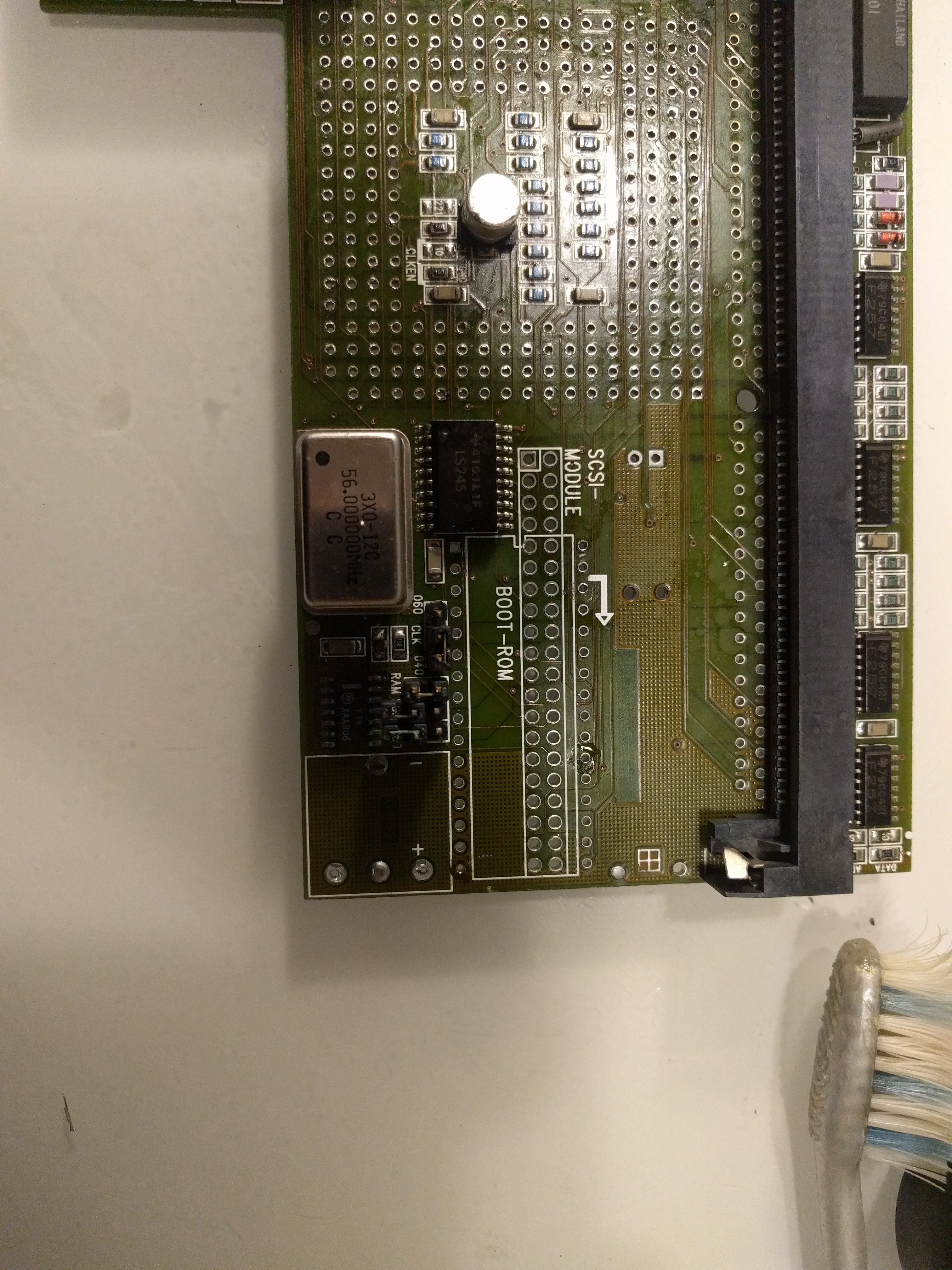
Frist the “usual” Before pics:
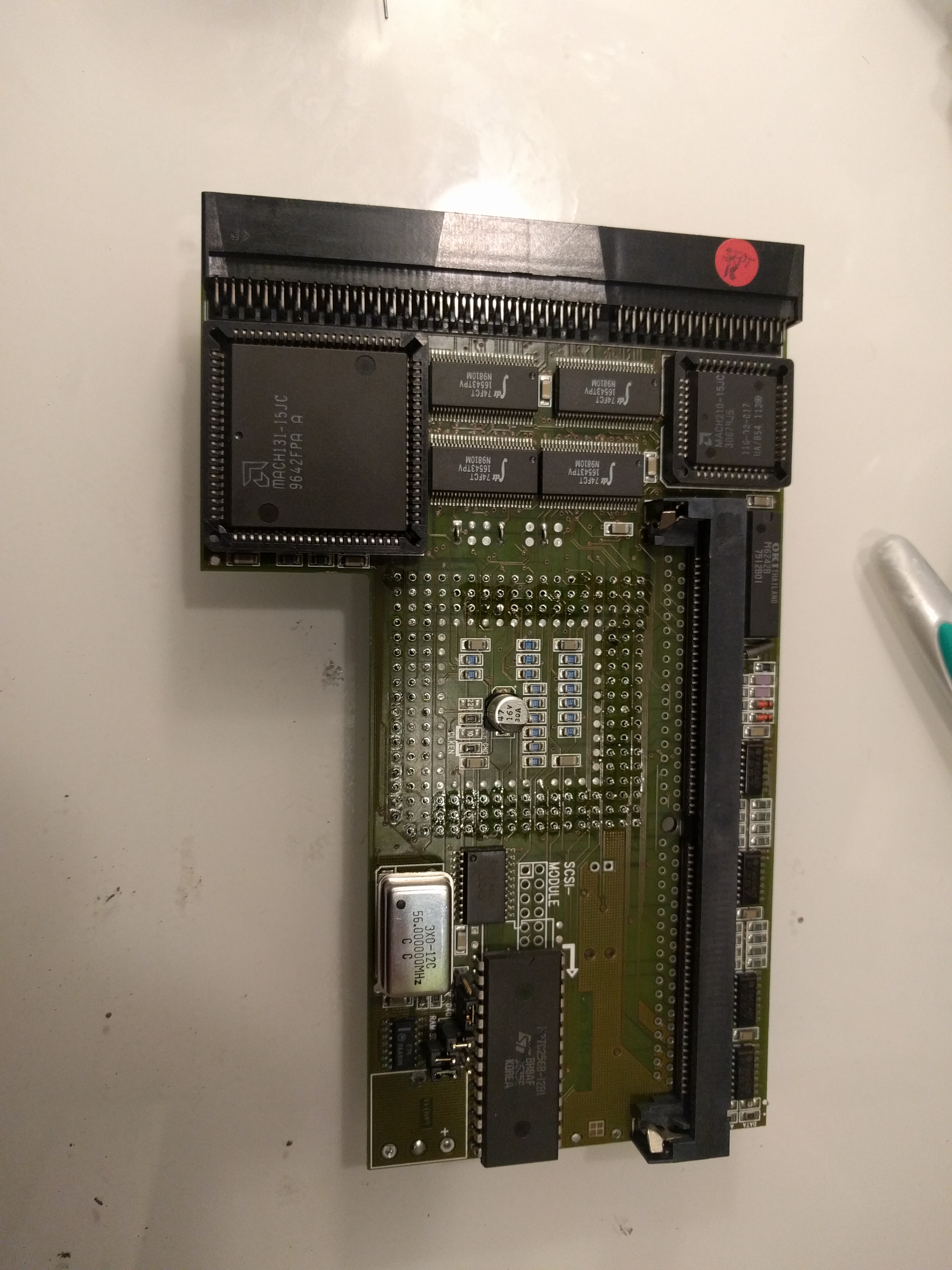
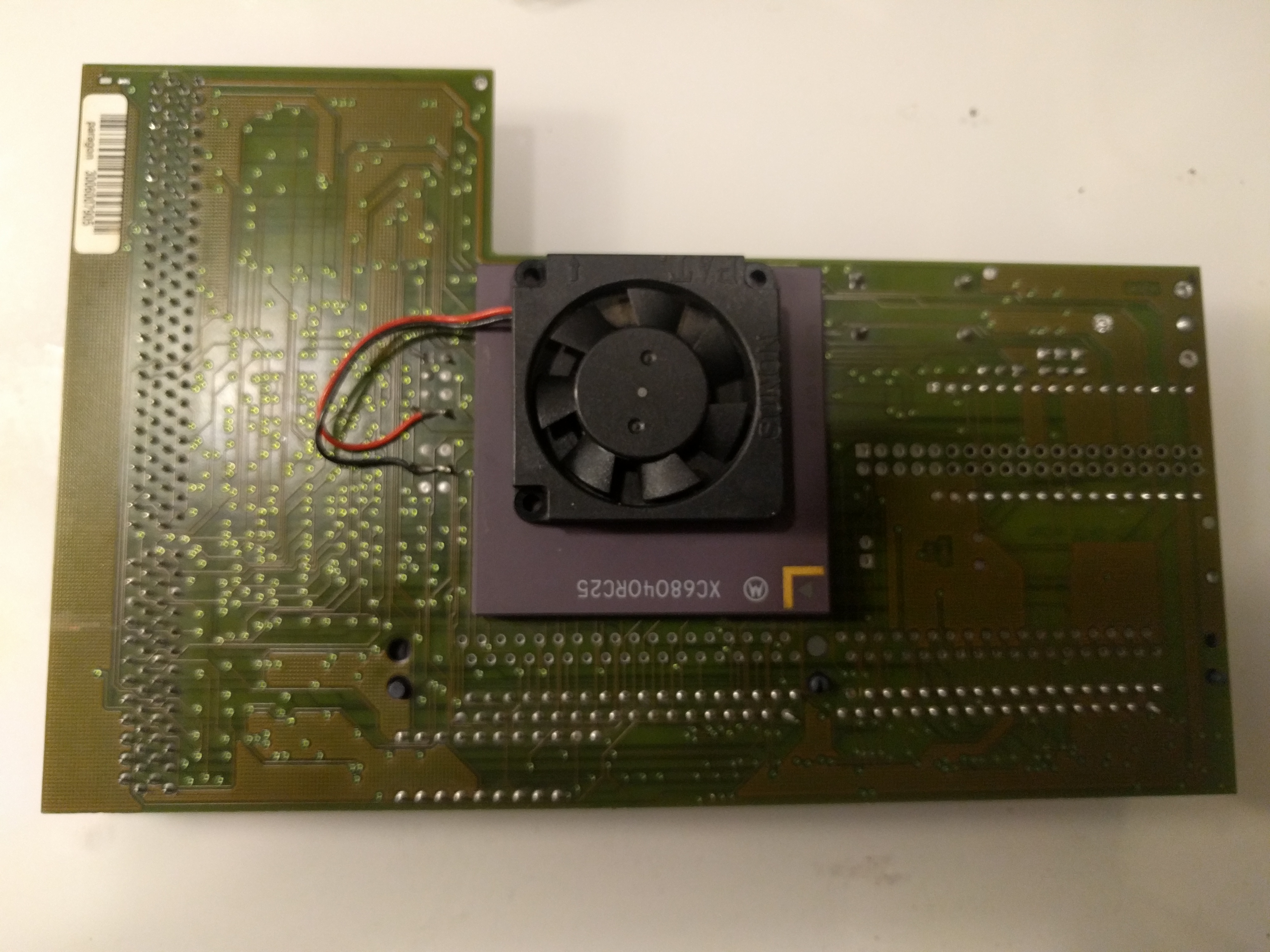
This is a 25MHz card with a slight overclock to 28MHz. (All 040 cards have the DOUBLE clock on the oscillator so this have 56MHz)
So it is time to remove the CPU. this is not a easy task, without the correct tools, you WILL brick your card. and the apollo have very small mountingholes so desoldering is harder than on the Blizzard.
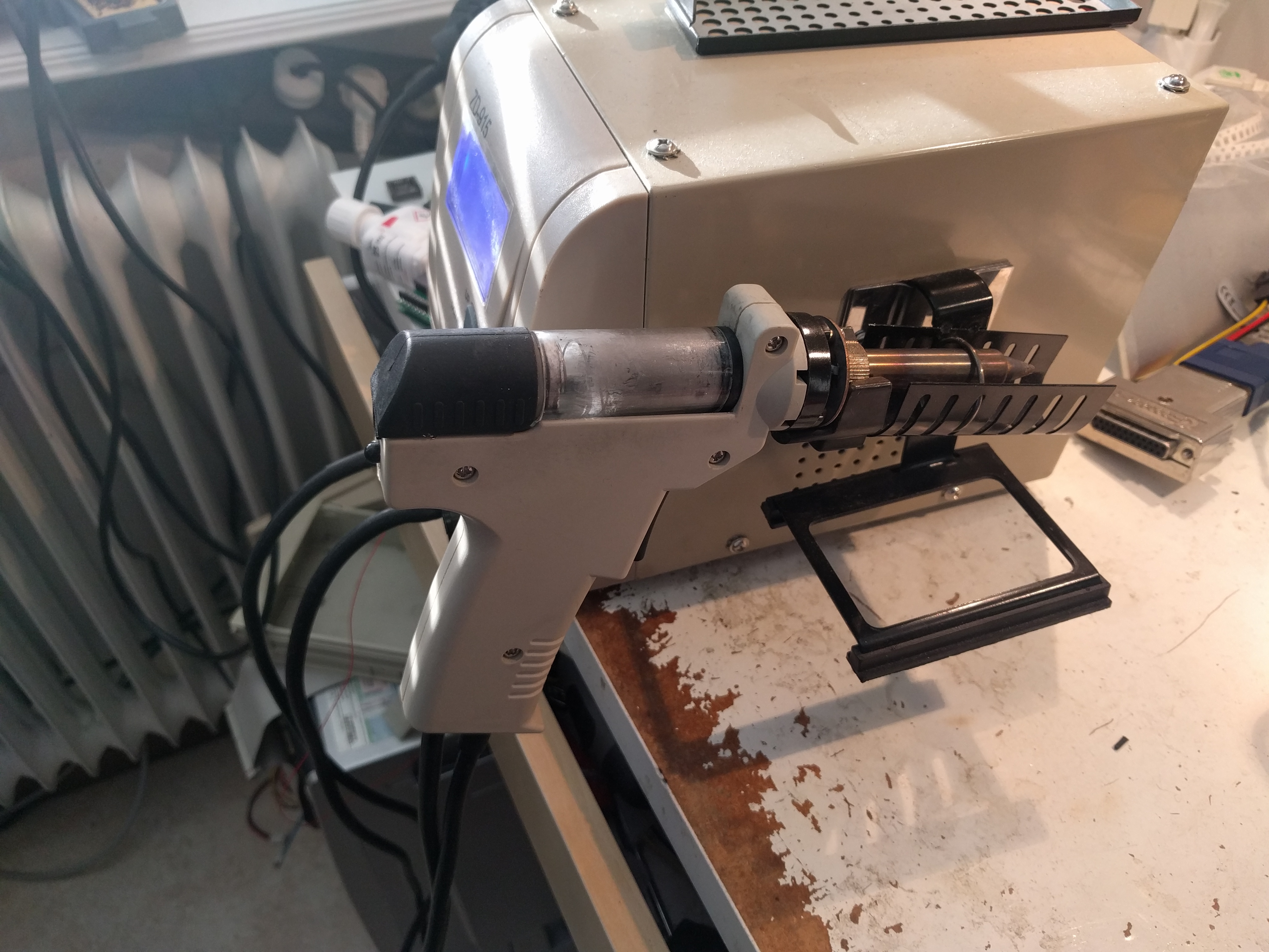
FORGET using hotair, solderwich etc, you WILL need a desolderingstation like this: (or simliar stuff)
So remove the cpu, and also remove the solder in the nonused inner “line” as the 060 have more pins than the 040.
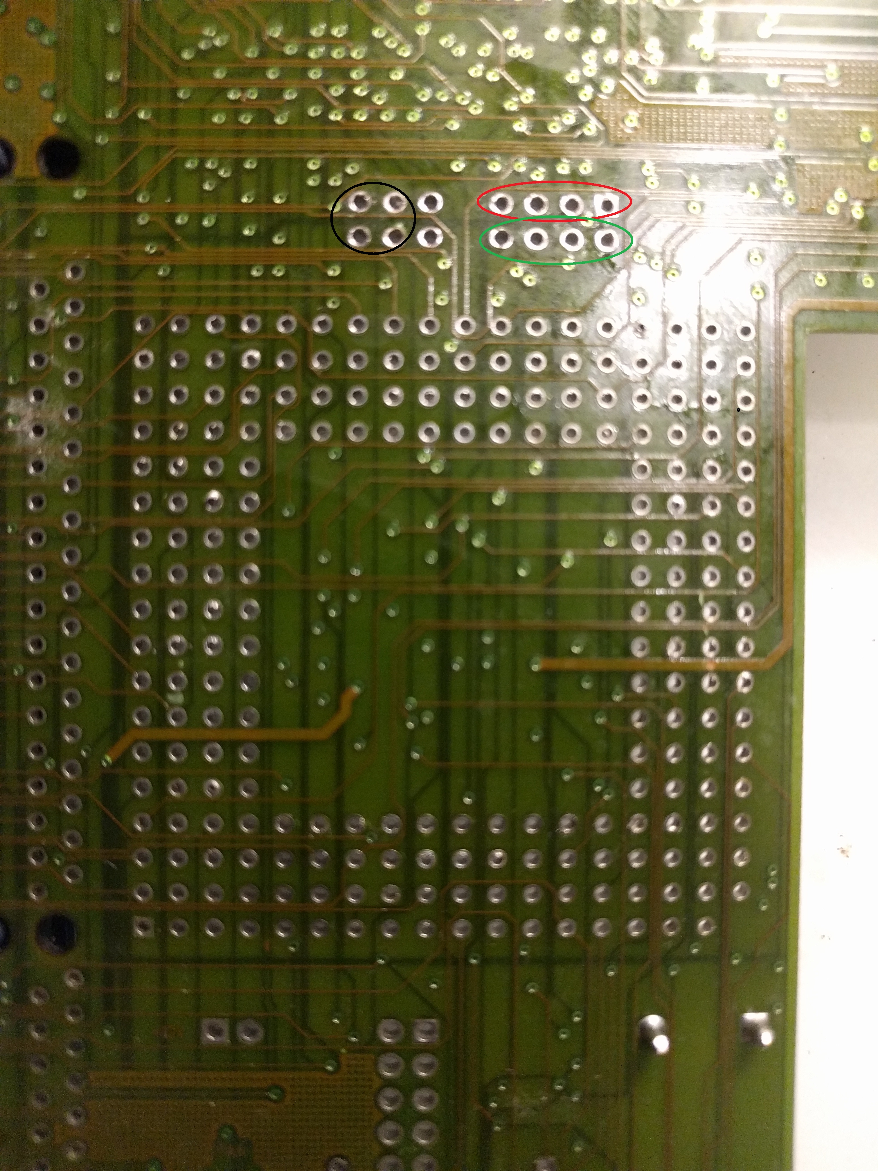
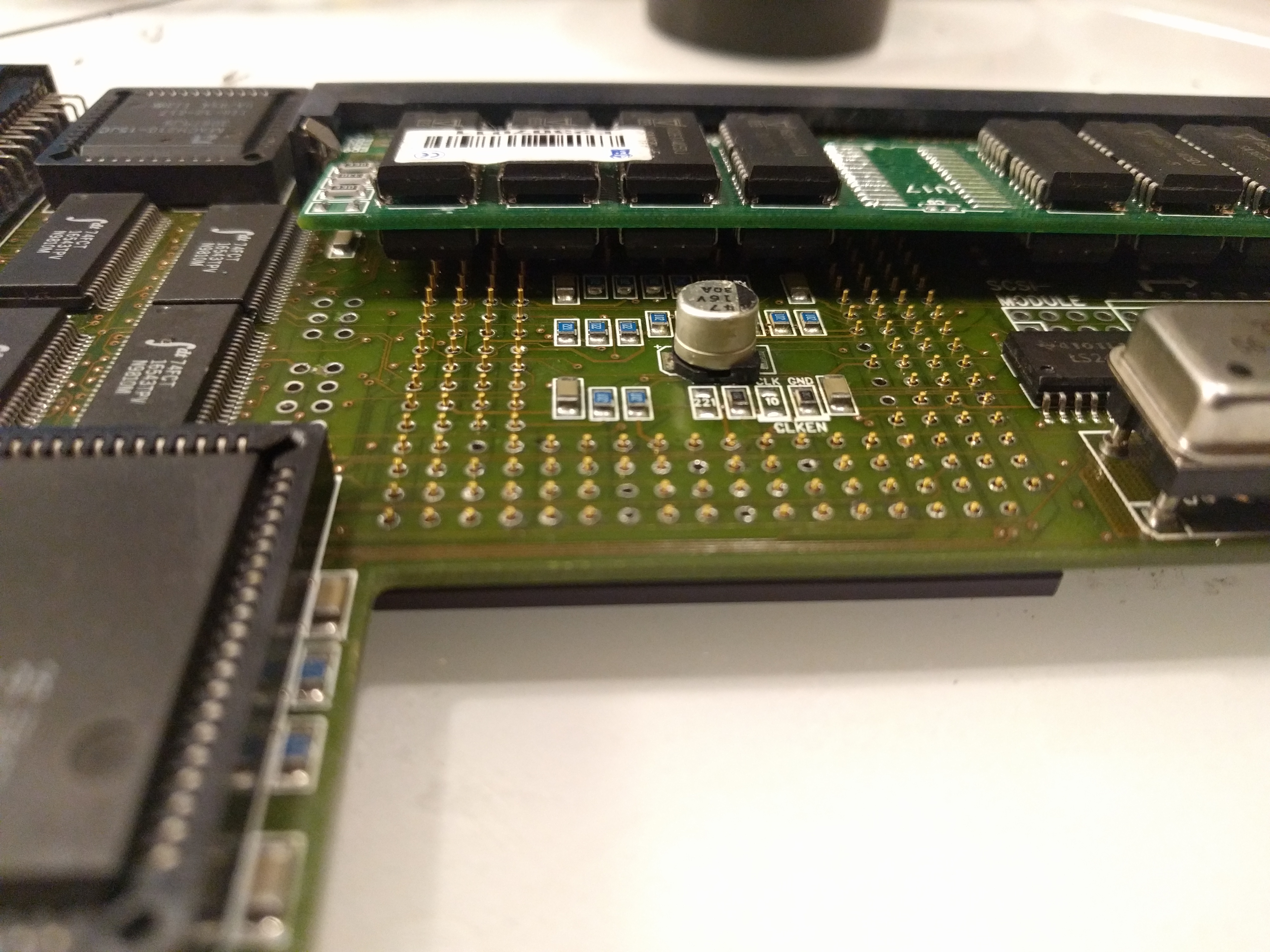
This is with the CPU removed (this is how it looks like below the cpu)
You can see on this picture thee small circles. they are important. you must also remove the small jumperwires solderd there. Those circles are important later. as the 68060 uses 3.3V instead of 5V as the 040 uses. the Red circle is where you have +5Vm the Green circle is where the CPU gets its power from. (and you just removed the jumperwires routing 5V to it. so basically now the CPU will get no power atall.
And the black circle is just ground. Remember NEVER to run a 060 cpu with 5V power.
Now it is time to remove the ROM Aswell, as you will need to update it.
Rom is removed. Now it is time to solder in the CPU. (you CAN add a socket here, you MIGHT get issues installing a extra simmsocket for desktopmounting if you do this) (more about this later)
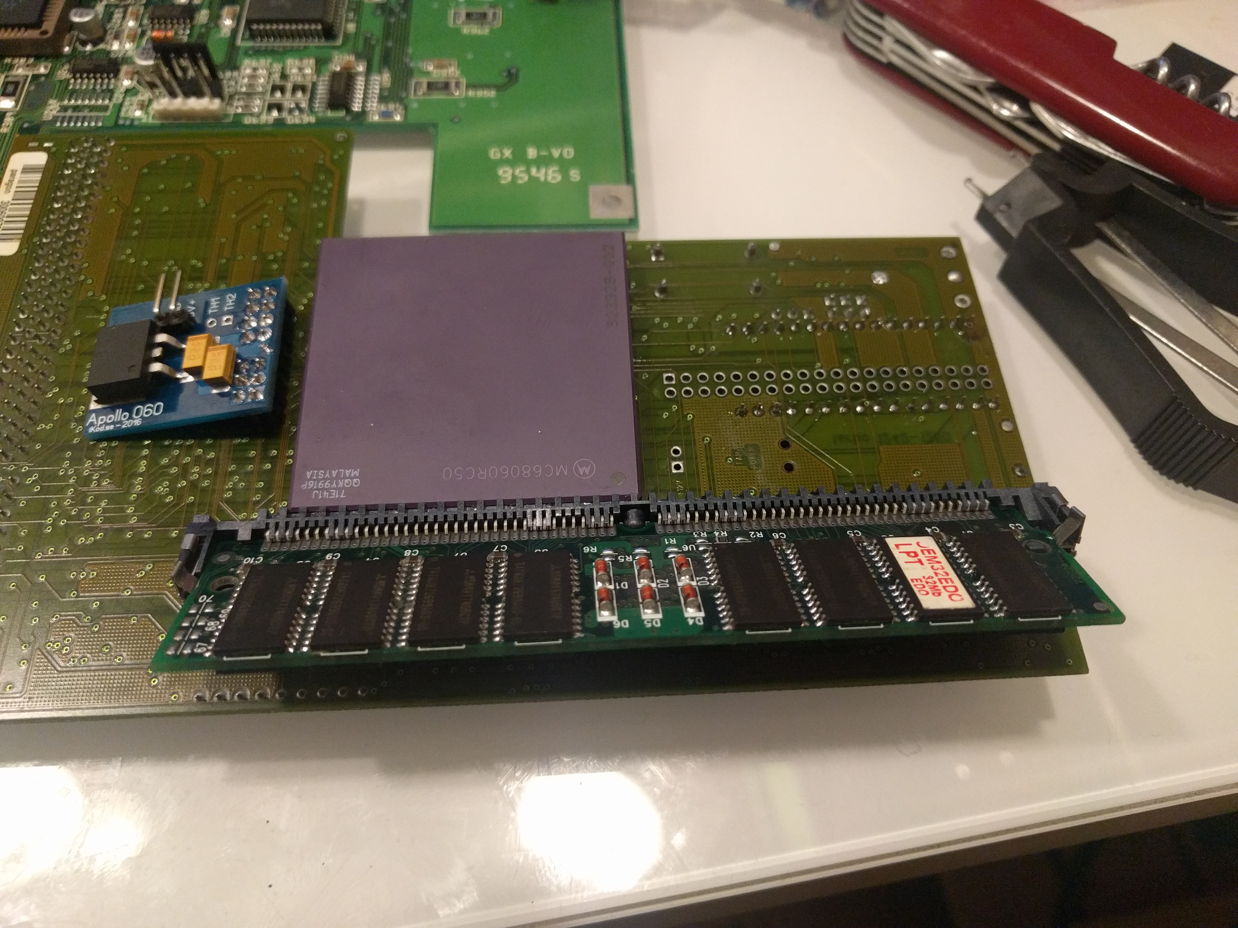
I usually put in a doublesided simm into the socket while doing this, by doing that I know that it will fit later with the cpu soldered into place.
Here you can see that I have a doublesided socket in place, and the cpu where it is supposed to be soldered in. Now time to solder the CPU in place.

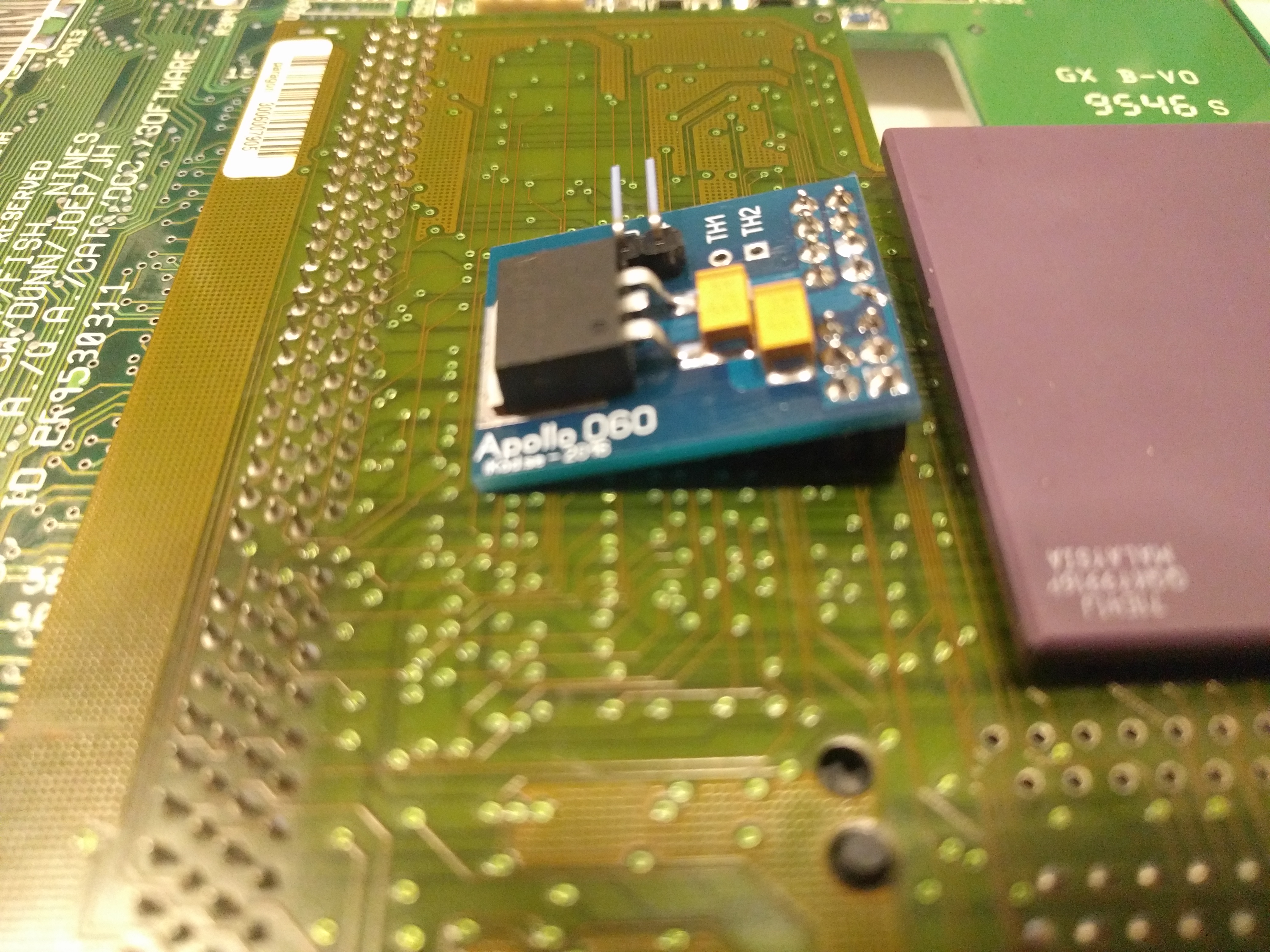
CPU is in place. Now it is time to get that voltagething done. AND on the Apollo this is way more “tricky” than on the Blizzard cards as you actually need to use a board for voltageregulation.
I use a regulatorboard from a friend of mine. Info about this is on his page: www.ikod.se A direct link to the regulatorinfo is found on: https://www.ikod.se/apollo-vr-12604060/
I usually solder it directly to the board so this is how it looks:
Now time to do the ROM. As Jens asked me to do it with a DIFF file only, you need to read the ROM and diff it out with bsdpatch. The Diff file can be downloaded by clicking here: Apollo060Rom
Burn the new ROM into a 27C010-10 Prom and solder it into the board. (there is usually NO space for a socket) you will need to clean up the 4 extra hols for the prom as this is bigger.
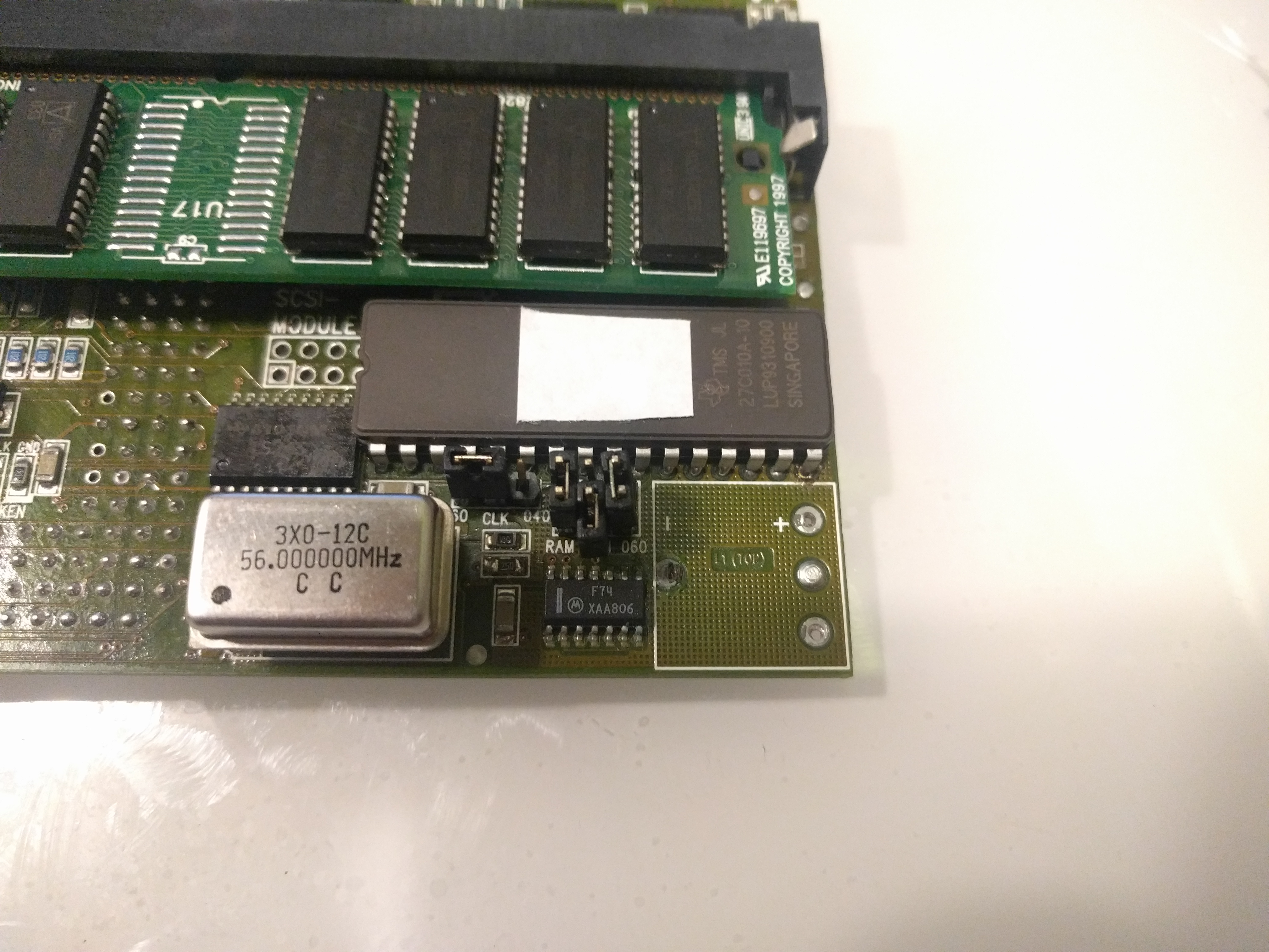
Now you also need to move the CLK jumper to the right to the 060 position, and put the 060 jumper in place.
And you are done.
So instead of 28MHz 68040, this is now 56MHz 060.
ADDING A EXTRA SIMMSOCKET
You CAN add a extra simmsocket allowing you to get 64MB of RAM into the board.
If you look at the card you can see a emply location for a extra simmsocket:
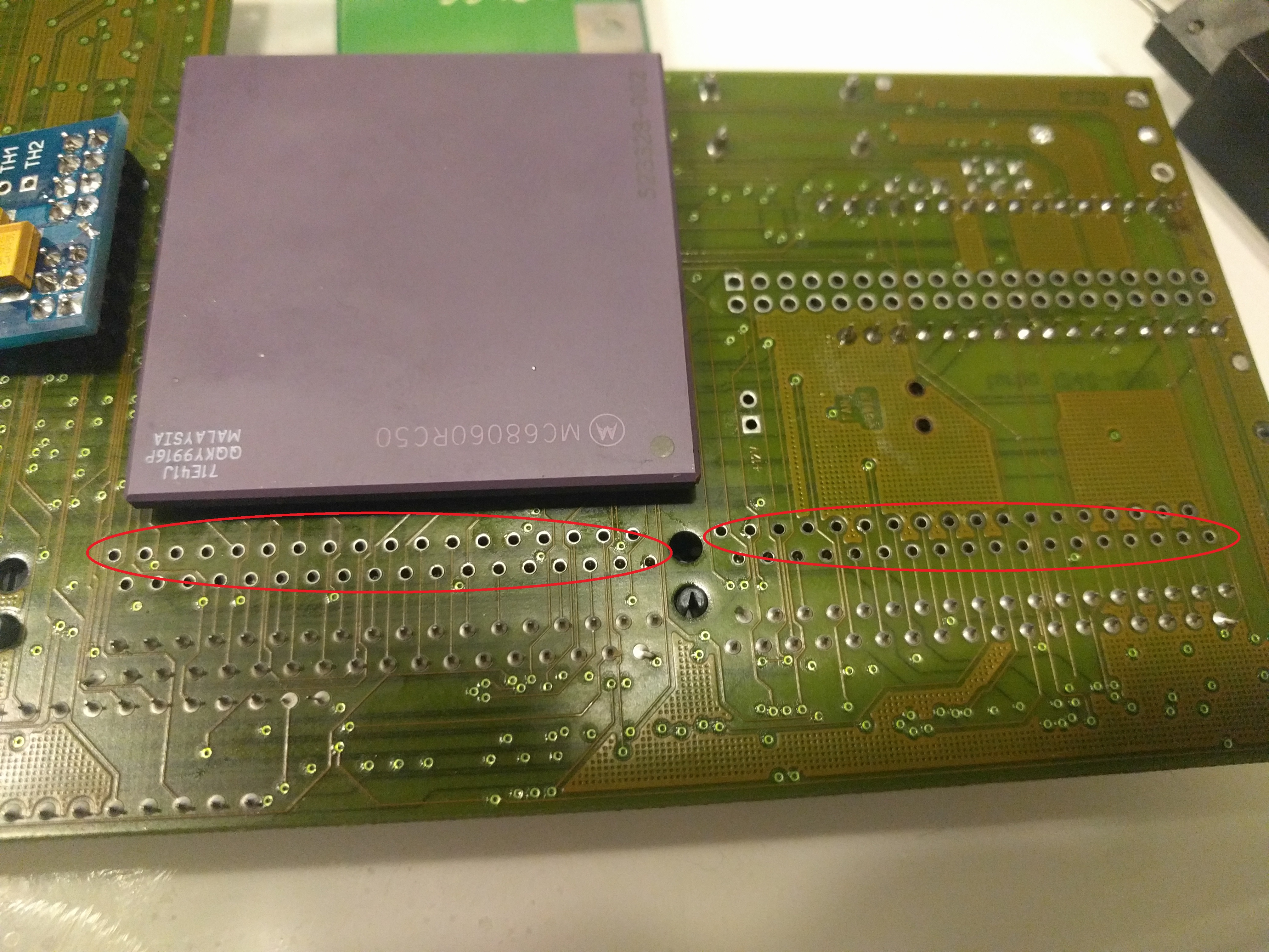
Here marked with Red circles.
You just have to solder in a simmsocket and you are ready to go to add yet another 32MB simm:
BUT! As you notice, this will make it totally IMPOSSIBLE to use it in a desktop A1200. This is solved in 2 ways:
1. Hack the simmsocket so you can put the simm in the WRONG direction (pin 1 to pin72 location), doing this lets you turn the simmsocket on the other way. put the simm in the “WRONG” way and with a slim 32MB simm, this will work. (but a VERY VERY tight fit!)
2. Use the Marmes 64MB hack and use a 64MB simm instead. You can find info about this at: http://www.amibay.com/showthread.php?72186-Apollo-1240-60-Single-simm-64mb-MOD-boards
OVERCLOCKING TO 80MHz
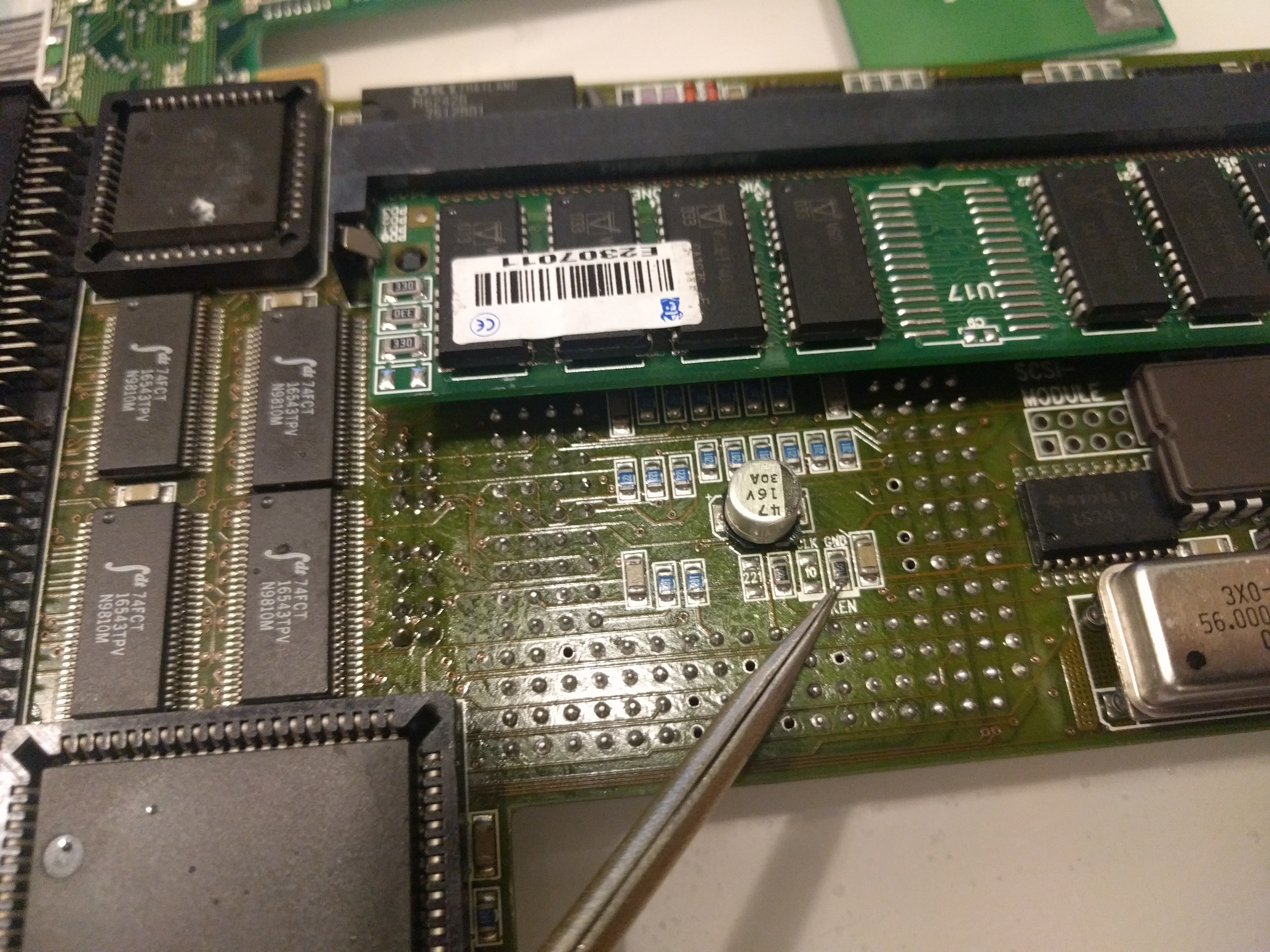
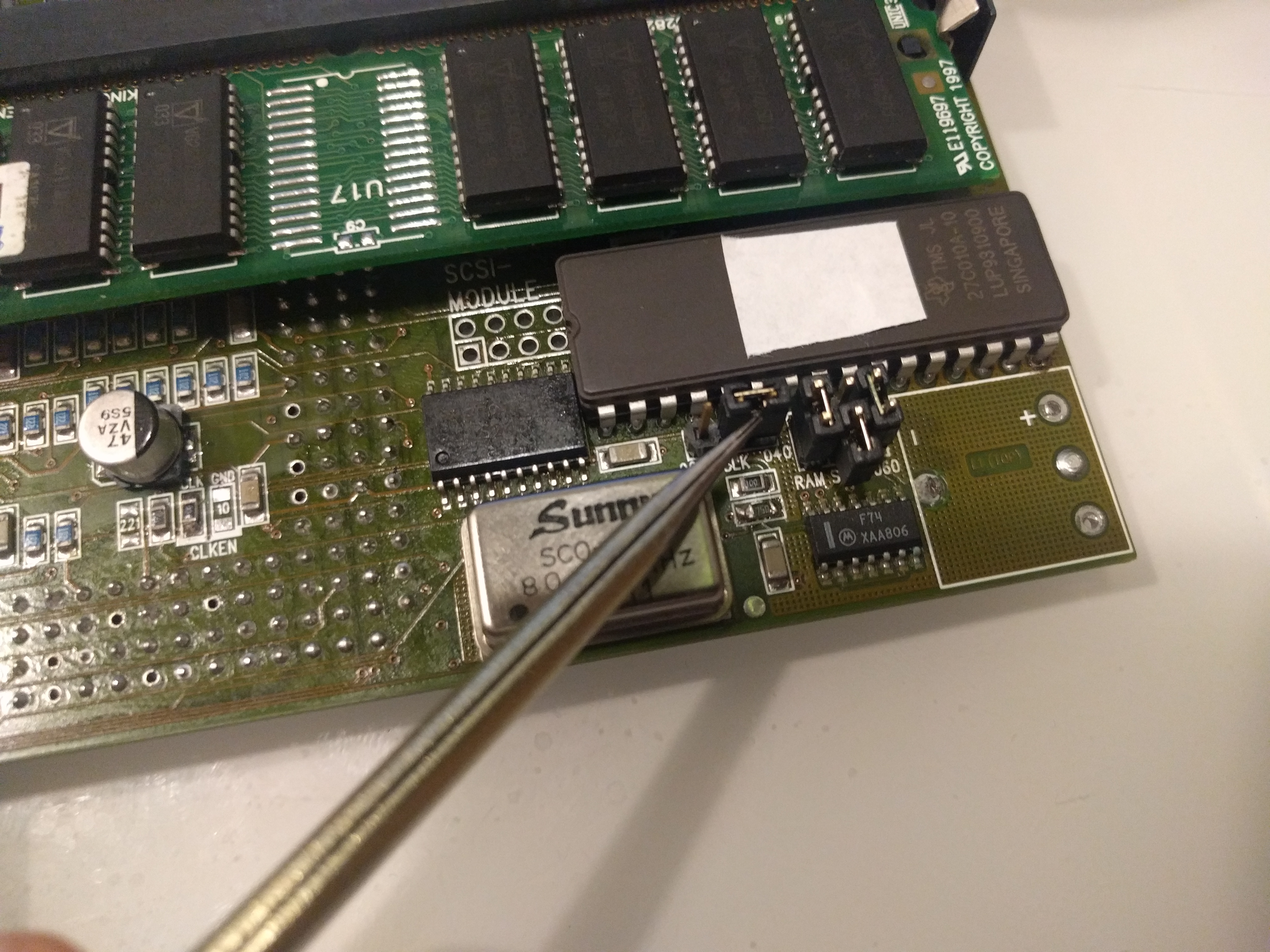
Well you CAN clock this to 80MHz (maybe more) by moving one resistor on the board:
from:
To:
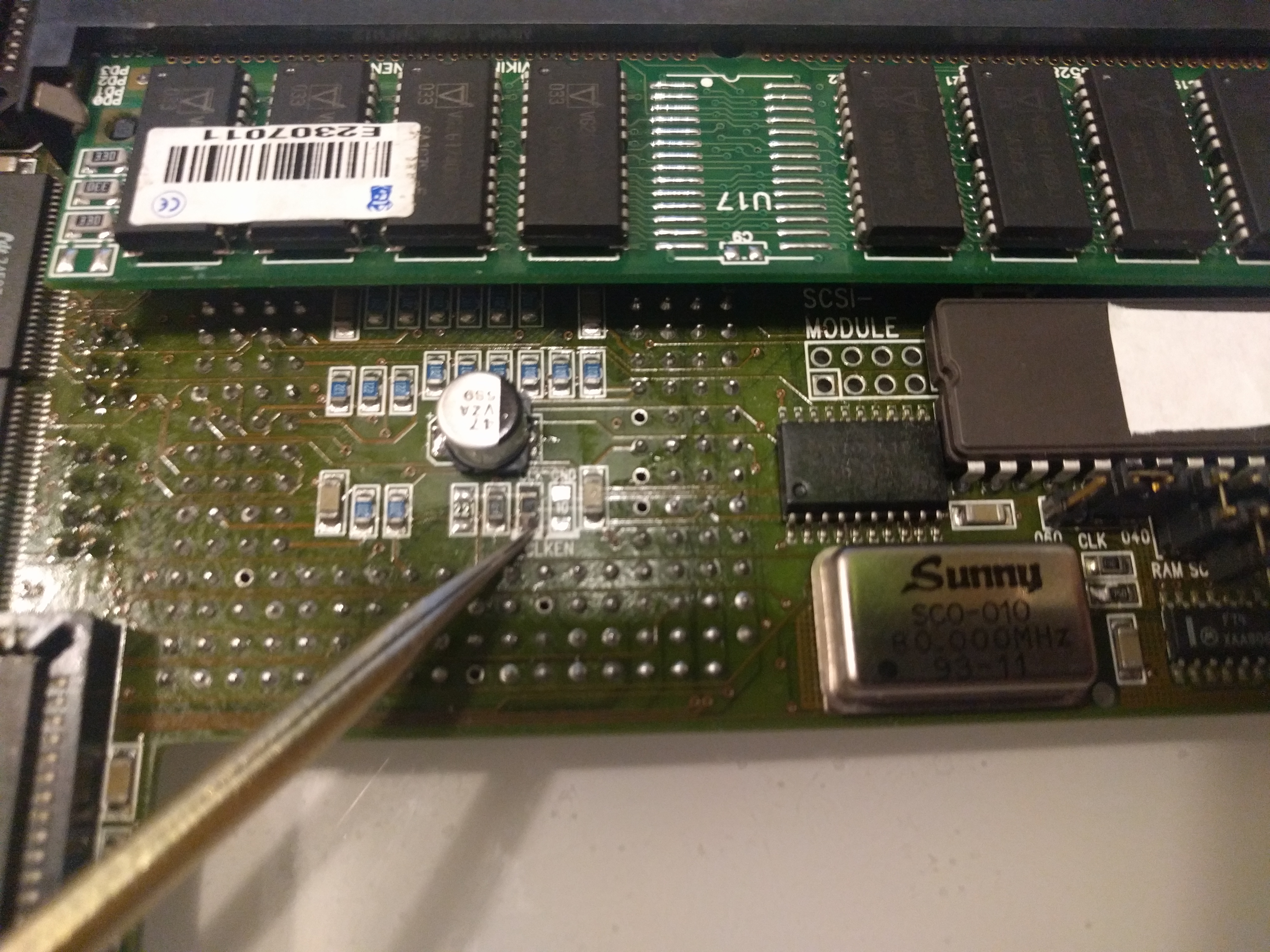
Doing this WILL lower the speed to the memory and is required or the machine will not boot at 80MHz. You can also see that I changed the capacitor on the board, I would recomend you doing this even without the overclock as they can leak.
this also requires you to move the CLK jumper BACK to its 040 position and also change the oscillator to a 80MHz one: (Remember if you had a 40MHz 040, you already have a 80MHz oscillator)
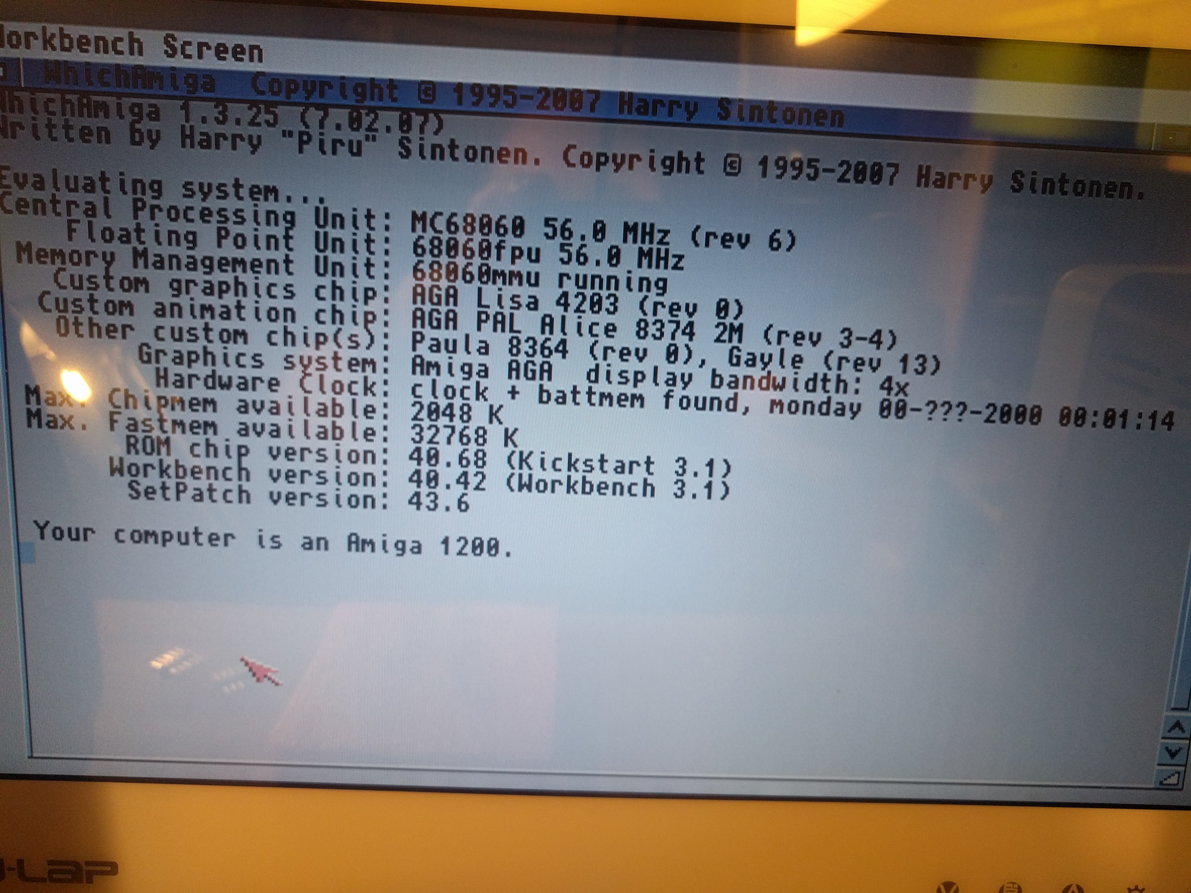
And power it up:

80MHz! but active cooling is HIGHLY recomended when doing this. also I would recomend you to try to cool the regulator aswell.