Building the ReAmiga 1200 from the ground and up! Part1
I decided to do a writeup of my build of my personal ReAmiga 1200 using NOS parts.
my plan was first to tell exactlty where all signals get up etc. but unfortunally this would simply take so extremly much time so I do more like “function by function” instead.
First, I decided that I wanted to go all BLACK!

First thing to do is to make sure the board gets Power. So lets add powerconnector. But just powerconnector will not do a thing, you need the filters to power the board.


Now when you have done this. the board have most of its powerrails done.
You can check +5 and +12V at the floppy power connector, and in this picture I also test the -12V connection by checking the right pad of C822:

Now it is a good time to add the led for +5V and also put in the components for the optional led, this is a led with a jumper above it. the right hole of the jumper is incoming. here you can solder a wire to anything you want that led to be used for. but usually you want it for the pcmcia activity, that is the left hole. but that we doesn’t do now. we just add the PNP transistor and 2 resistors. we can use this for other stuff later.


Now when we have power done and a powerled. (or well. +5V power led.. nothing to do with the machine)
Lets time to add the interesting stuff. The first and most important thing on the 1200 is the 28MHz oscillator.
And on this machine, the only old component.
You need to solder in a ferrite bead at FB992 or the oscillator will not get any power. then solder in the 28MHz oscillator.
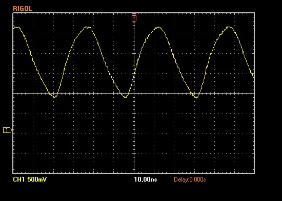
on the picture you can see me pointing with my oscilloscope probe on a via. this is not a via I forgot to hide. it is just a way for me to remember where it is. to test that the oscillator is working

Power on and my oscilloscope shows:

A nice 28MHz wave.
Now this signal will end here. You need to add E131R so it gets to the budgie chip. This alters the signal slightly.

And Rev2 boards have a 470Ohm resistor at R100 as a pullup, Rev1 boards doesn’t have this. I added this to the ReAmiga, then the signal looks like:
Now it is time to add the first real chip. The budgie.
on boards with ENIG finish (gold) I found out that putting solder on the pads first helps alot when soldering on the chip:

Blobby! then clean it up:

Put in the budgie and solder it into place in one corner:

Then on the opposite corner, when it is all aligned. start putting flux on a side you haven’t soldered on:

And then “just” do plain dragsoldering solder the chip into place:

Now when the budgie is in place we will have another output from it. a cleaned buffered 28MHz that you can measure at E133R on the bottom side:

now put in the resistor at E133R, as it feeds the LISA.
So.. lets put her into place:

and under the LISA I populate E377R, E377C, E376C, E376R, E375R and E375C so lisa can communicate with the “outside world” some.
And also put in Gayle.
Now for the next step (and end of this first post) is to get a Video sync out of the RGB port.
So lets ADD the VGA port. (or the RGB port.. but I use the VGA here)

Remember that this VGA port STILL requires that your monitor handles 15KHz, my labb monitor does this.
Also you need to add the resistors at E251R and E252R, so the V and H Sync signals can be forwarded to the monitor.
Now I also added E112R, E122C, R114 and E129R, E129C, E126R, E126C, E127R and E127C.
now I got a SYNC on the monitor. (actually when populating E127R did this so all other passives before that can maybe be skipped)
However. this is the minimum to see if there is SOME KIND of working chipset. You cannot be sure, but it sure is a good hint. If your monitor does not give a sync here, your machine WILL NOT WORK and you need to settle this first.
This is it for today.. lets see when I do the next part.