Building the ReAmiga from scratch. Part1
I decided to rewrite my post about how to build an ReAmiga from scratch. It simply was too much work to do it resistor by resistor..
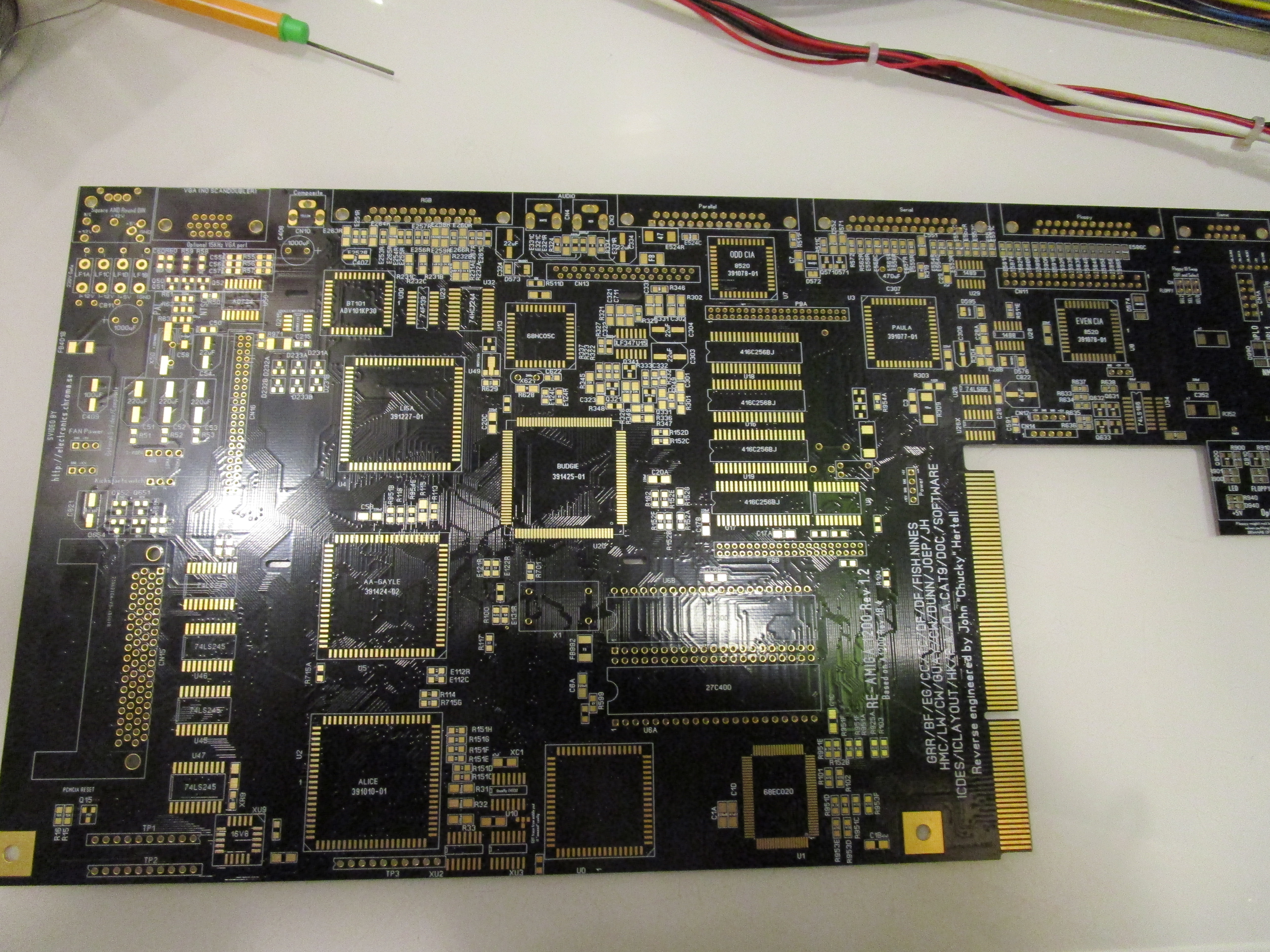
So first, I decided what board to use. And well Black is nice. so that I will use here aswell:
So first, load up the locator at http://www.hertell.nu/locator/locator.php?project=r1200
at Multi, choose “Resistors” and from your pile, pick up one of your packs of resistors.. like 68Ohm choose 68ohm from list:
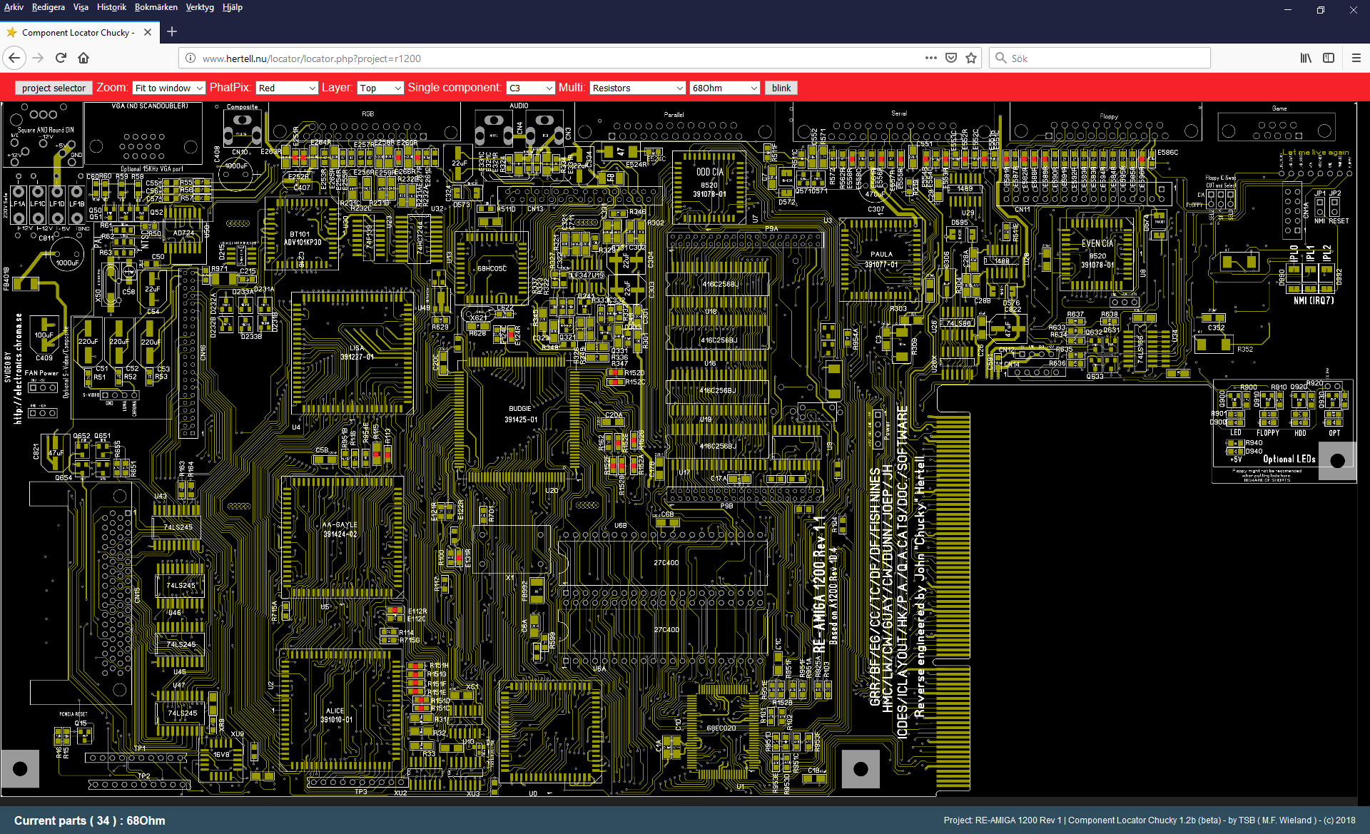
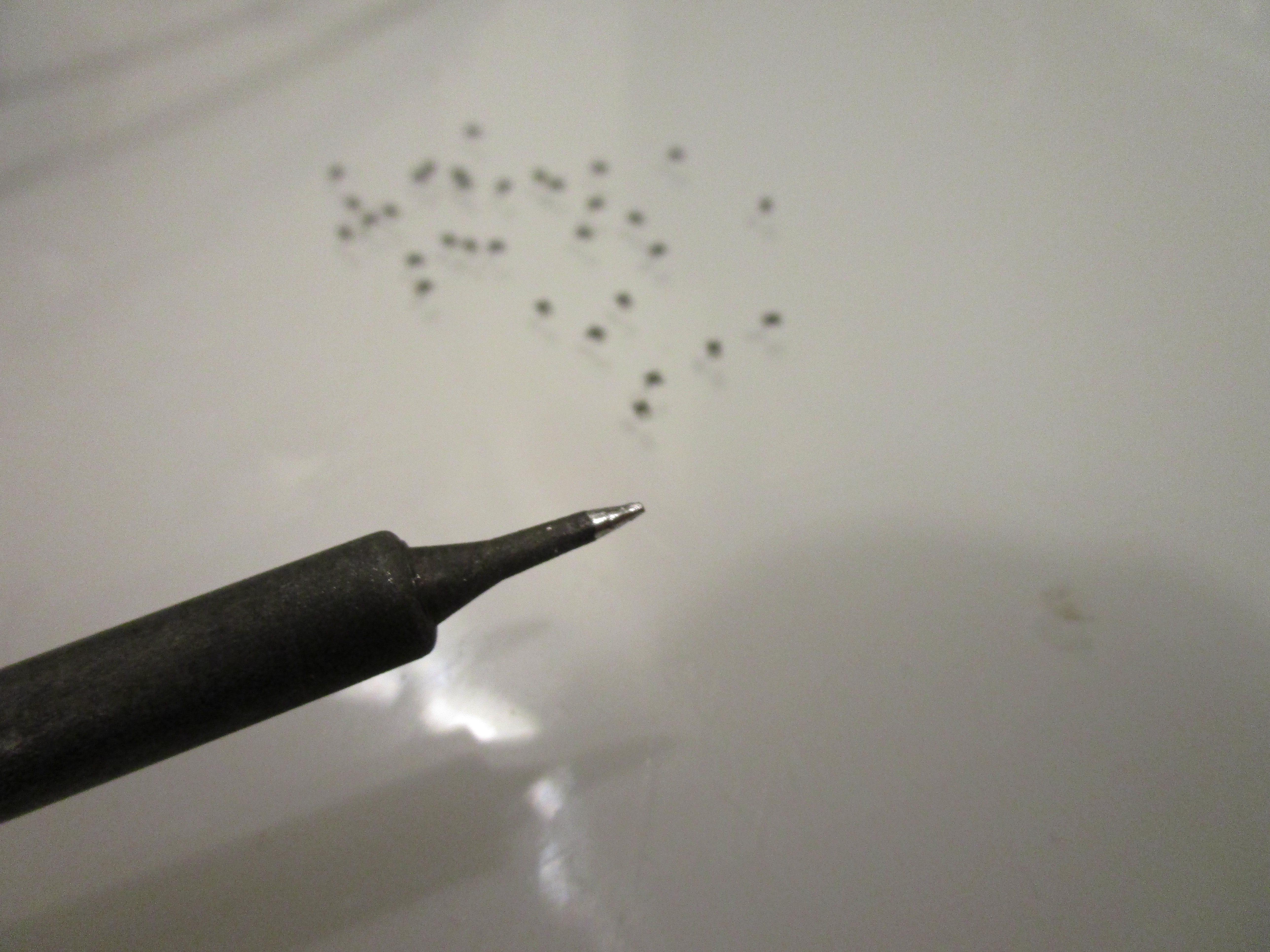
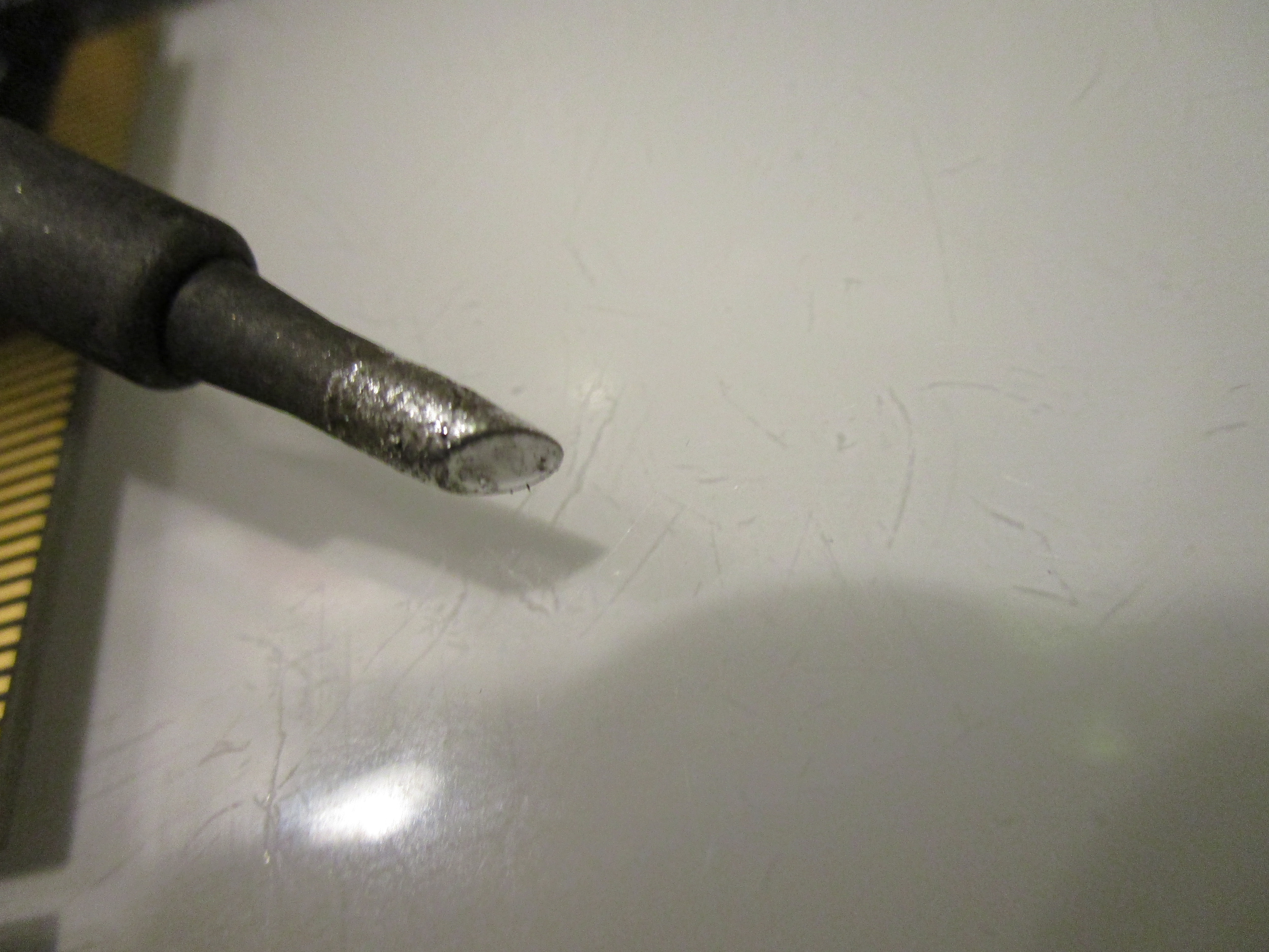
Here you can see in the lower left part that there is 34 of them on this side of the board. So I usually take out 34 of them, sort them facing up on my desk. and start soldering, with a thin tip like this:
After doing all resistors on the topside, I do all caps:

And then the same thing on the bottom:

for the moment, ONLY do caps and resistors. skip diodes, transistors etc.
endresult will be something like this:
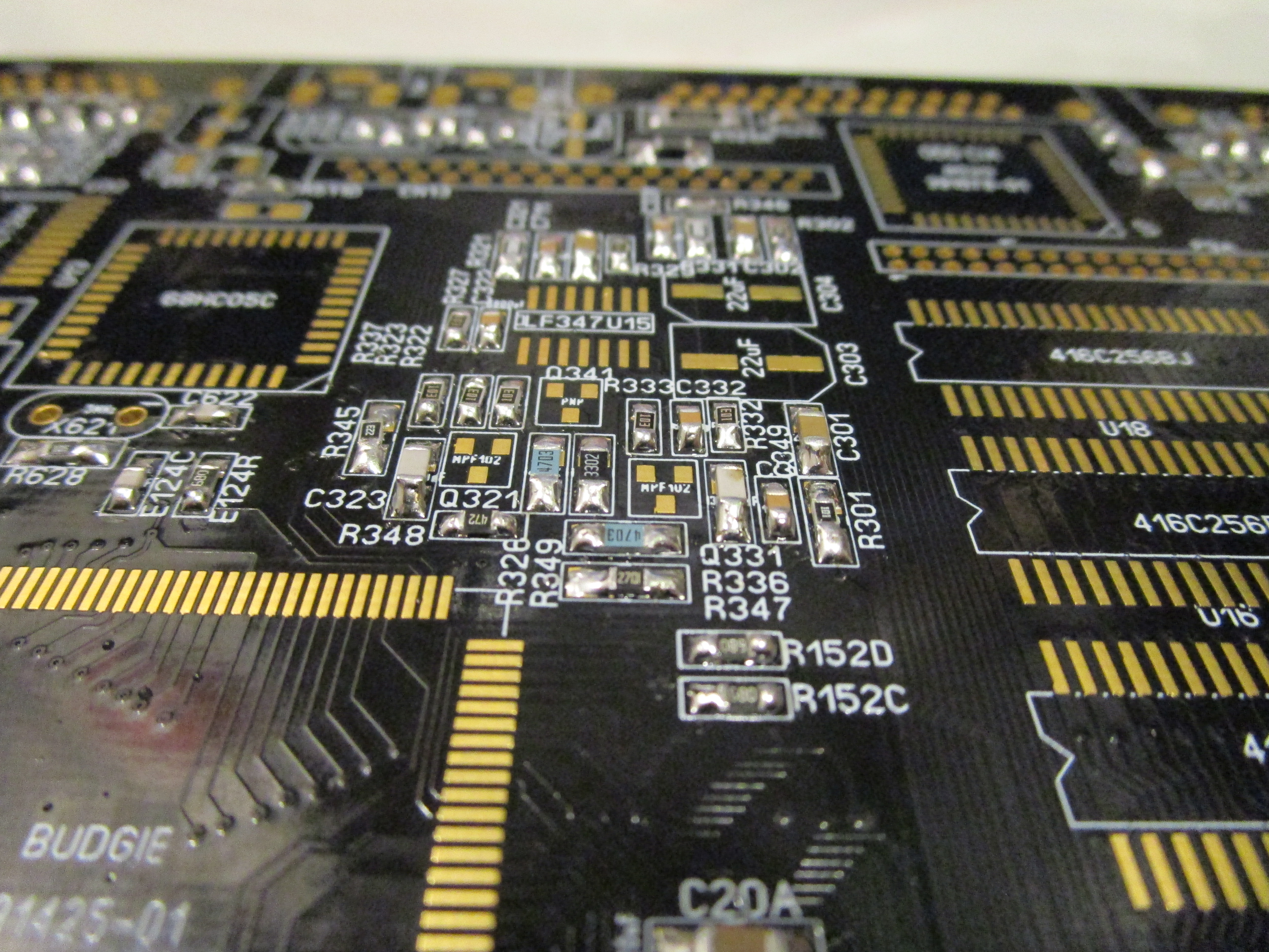
Anyway. now with all the “birdseed” on place, time to get started with the real thing.
but before that. do take a look at the errata post I did: http://wordpress.hertell.nu/?p=710 as you might need to do changes on your board. I am using a rev 1.2 while doing this.
First time to start with the power:
Add the powerconnector (NOTE! ERRATA! if you have a Rev1.0 PCB. you now need to do the cutting on the trace or you will get a short)
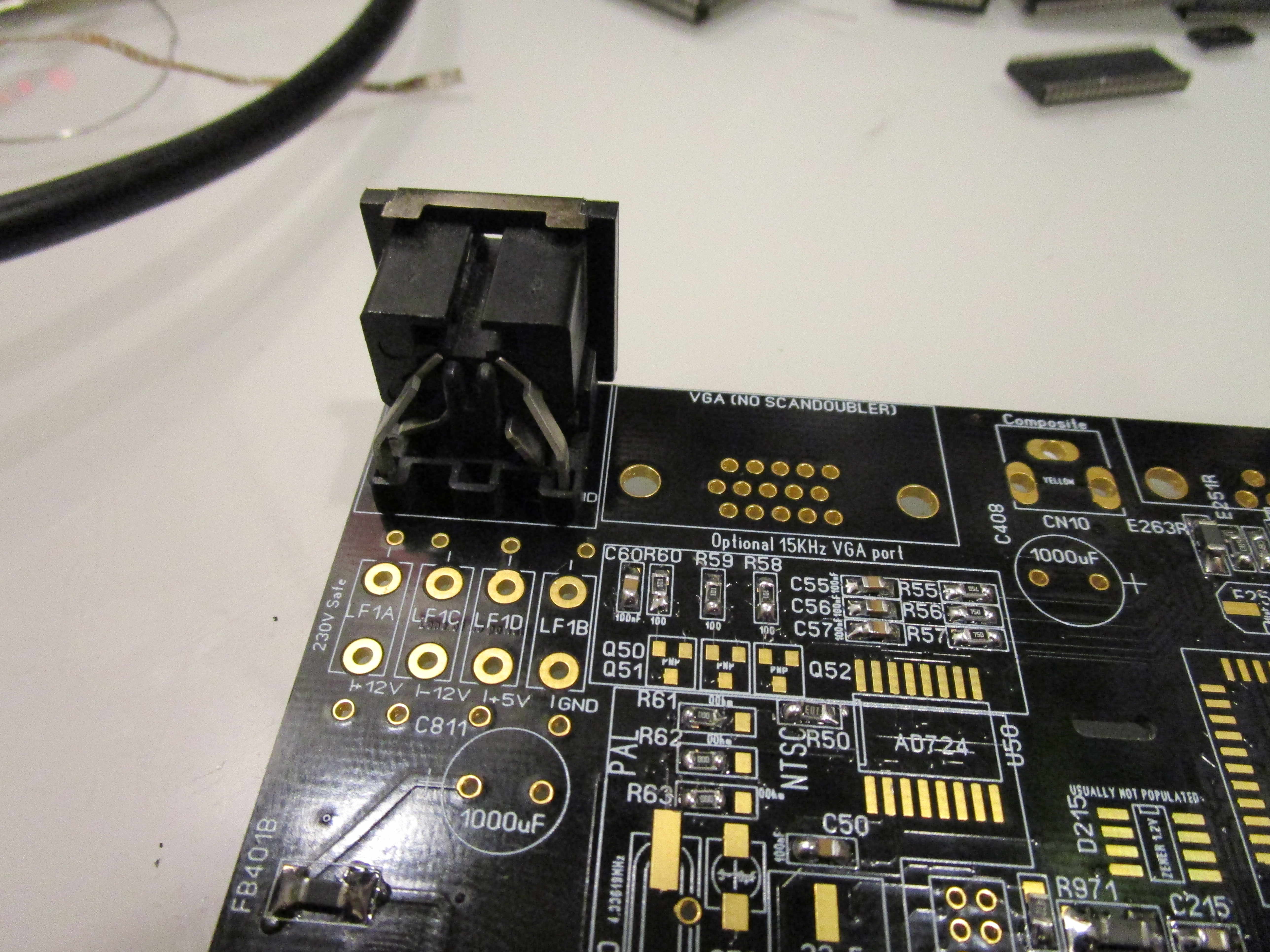
This will however not power up the PCB as you need to add the filter:

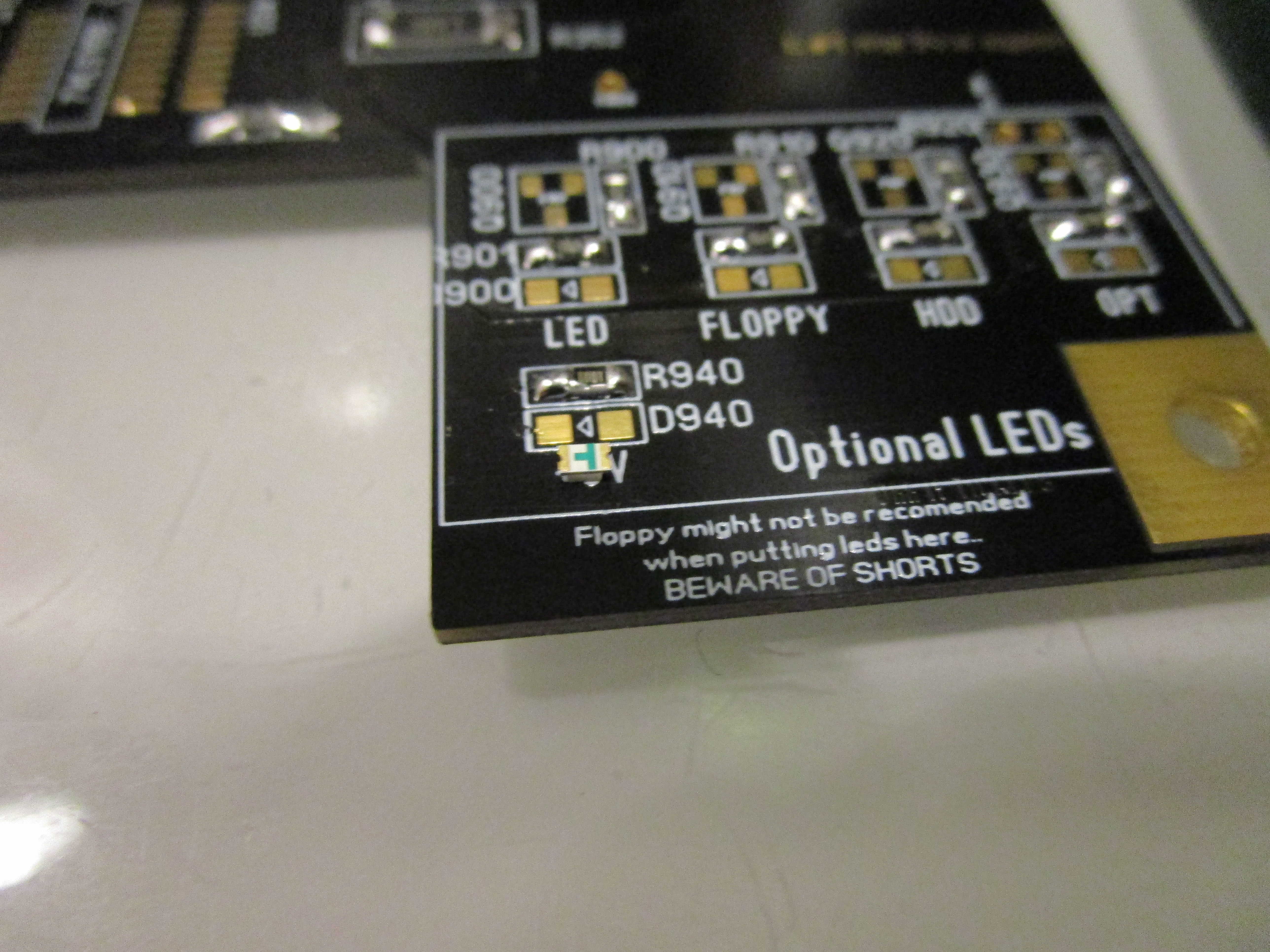
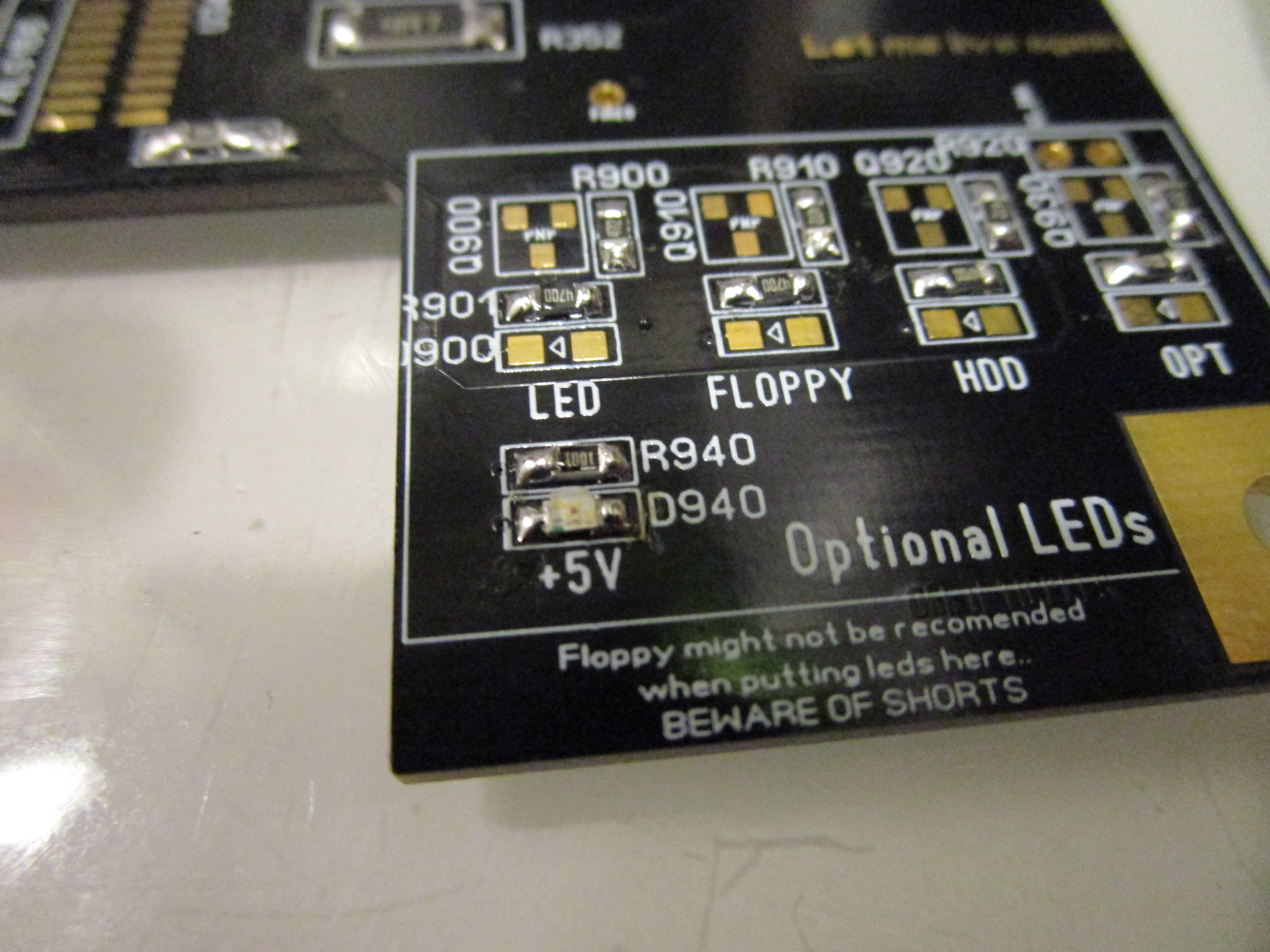
To see power lets add the LED. first picture I have turned the led upside down. so you can see the small marking facing to the left.
and the arrow on the PCB facing left. This is the direction the led should be soldered in. SOME leds have a small marking on the topside aswell.
Time to power it up:
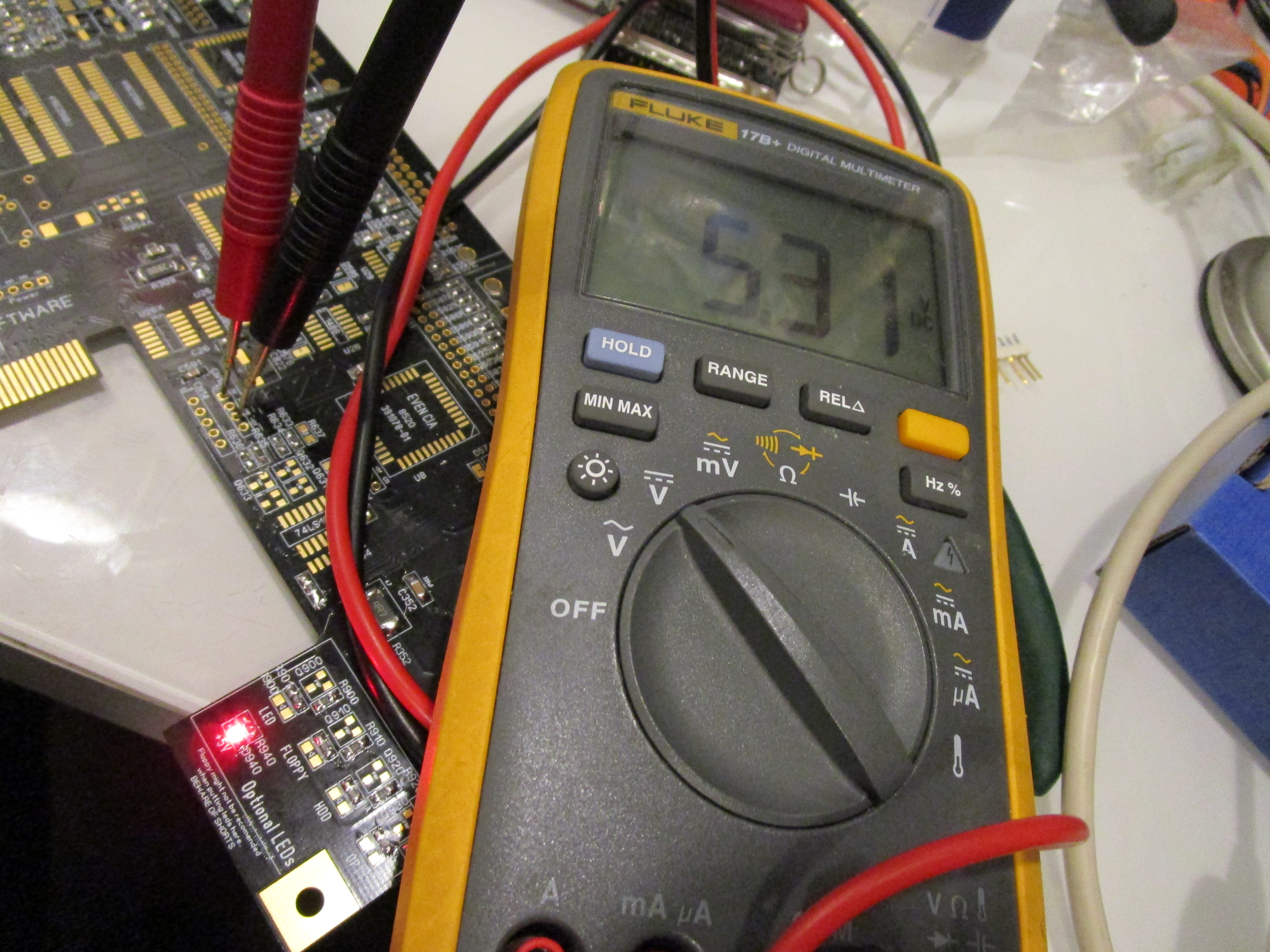
Led should be bright and you can measure the voltage on the floppy power connector. Slight overvolting is normal with no real load on the board. do not worry. -12V is located on the right part of the PAD of CAP C322 close to the powerconnector.
Now, lets add the diodes C324 etc on the board. they are there for protection so lets begin with them:
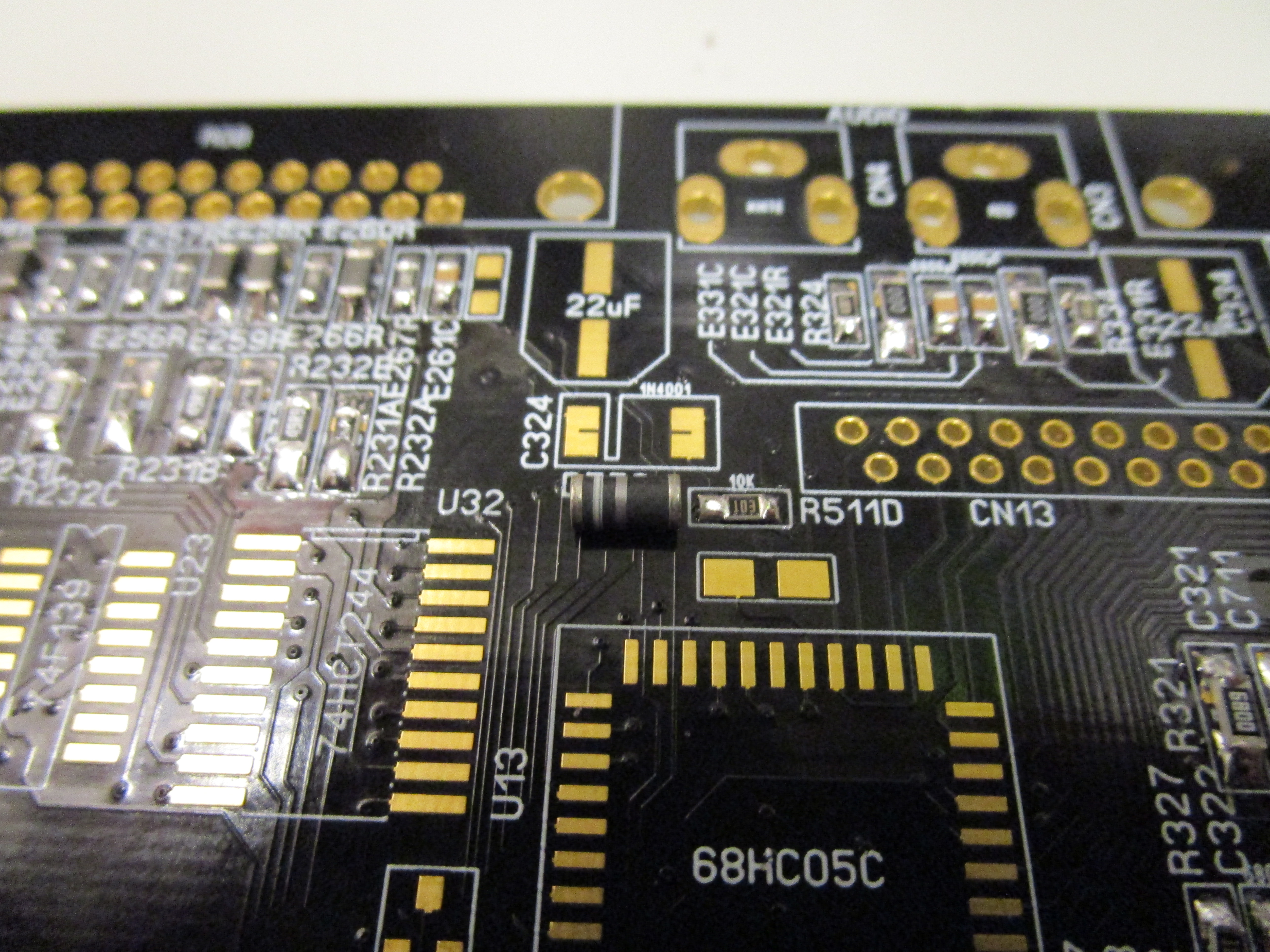
Here you can see that I have placed the diode in the direction if should be there. take a note of the silkscreen print and diode.

Solder it in. do NOT solder in the diodes at the NMI location. only the rest.
Now. add the 28MHz oscillator:
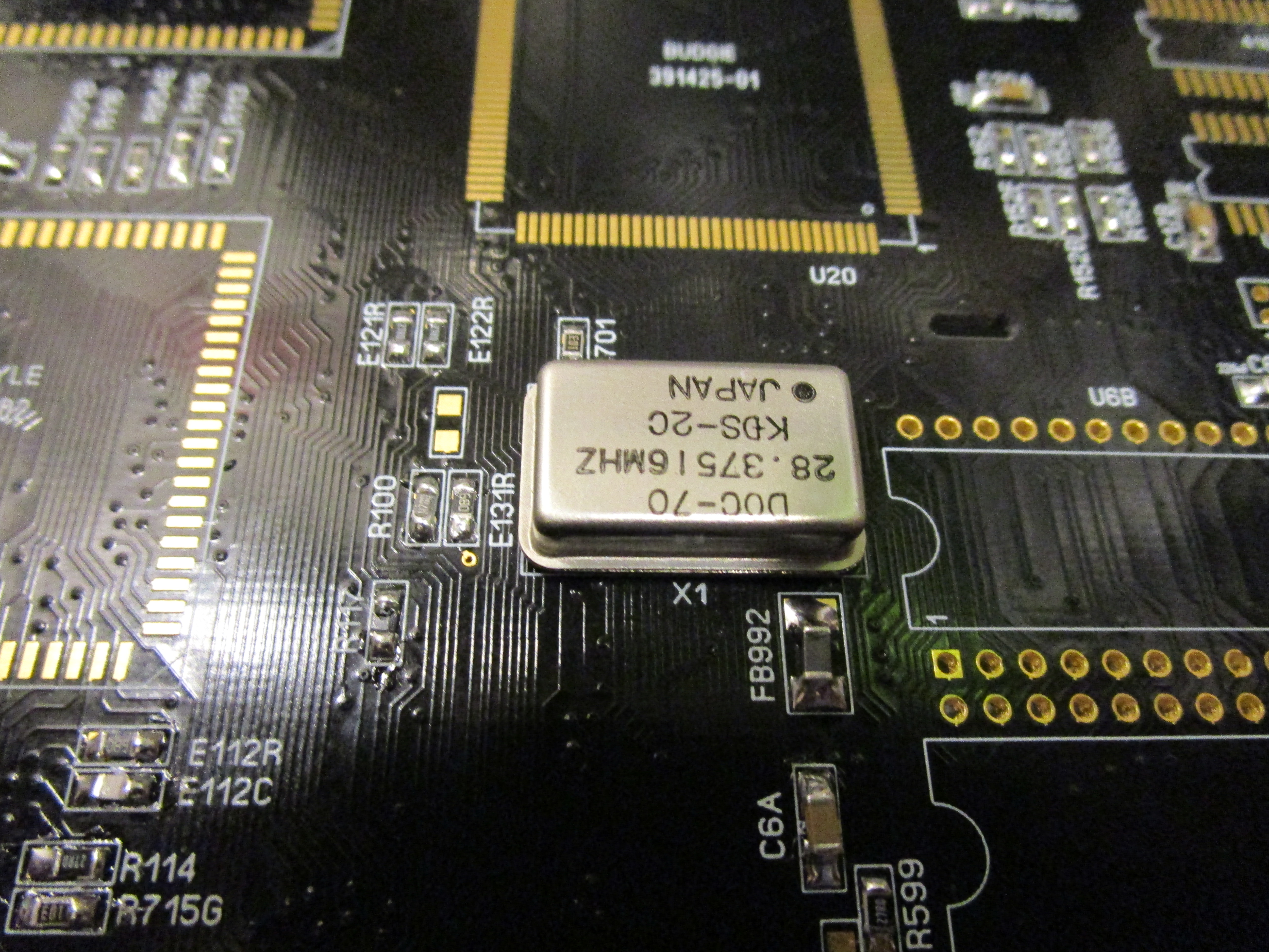
You can see that I have “forgot” to mask one via to the left of the oscillator. but no. this was not forgotten. it was a reminder that here you can probe it with your oscilloscope to see if there is a 28MHz signal here:
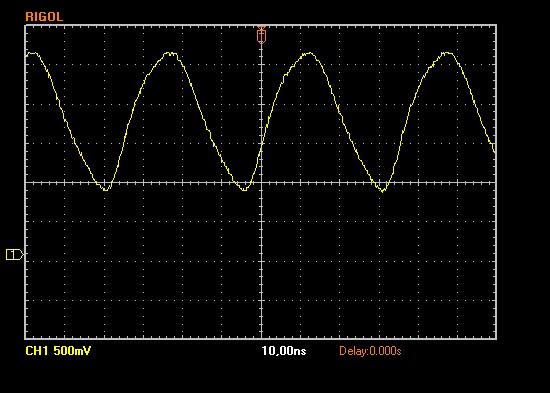
And YES. 28MHz. next step is to solder in the budgie:
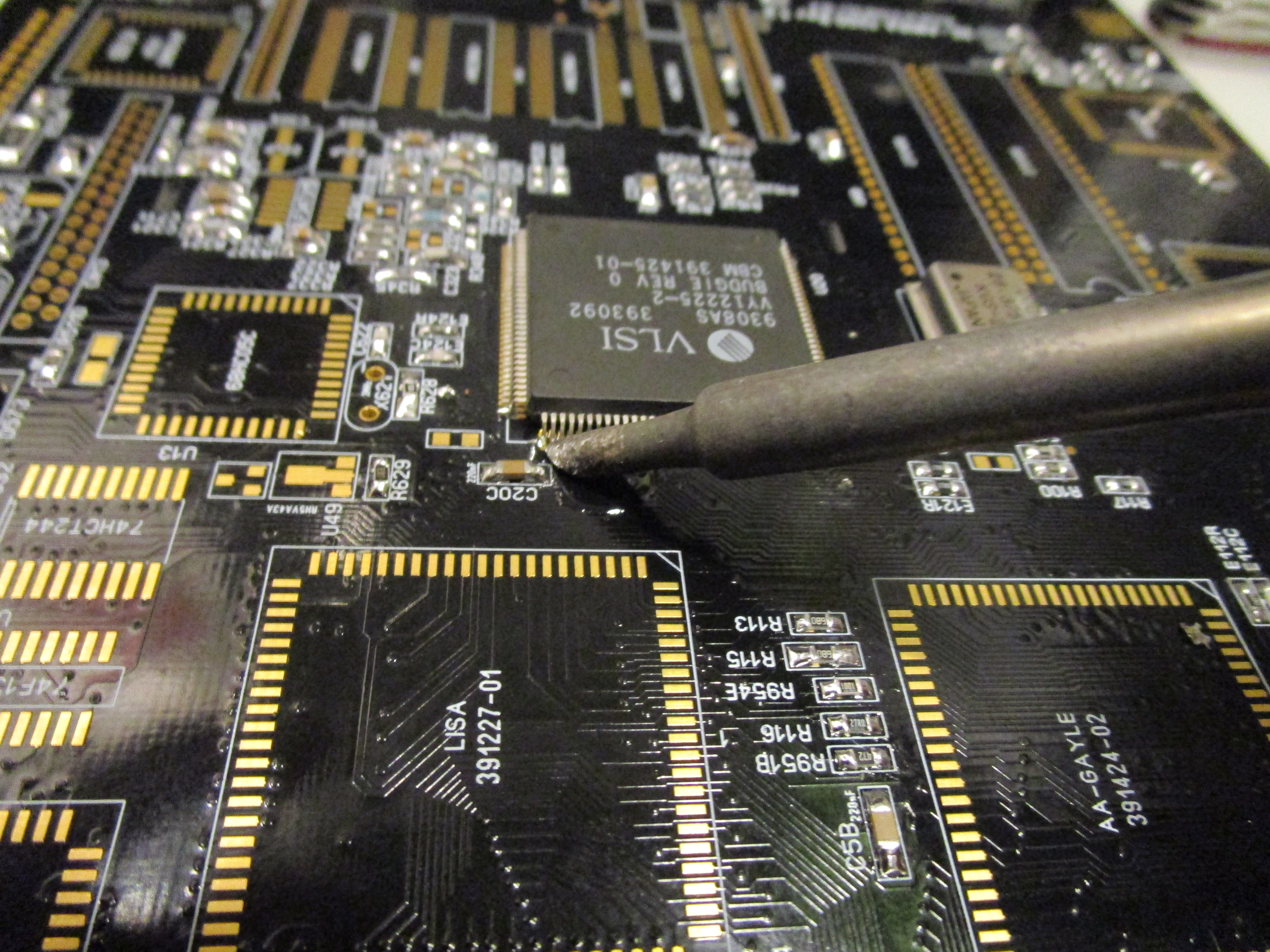
For this I use another tip on my iron that helps me do dragsoldering better:
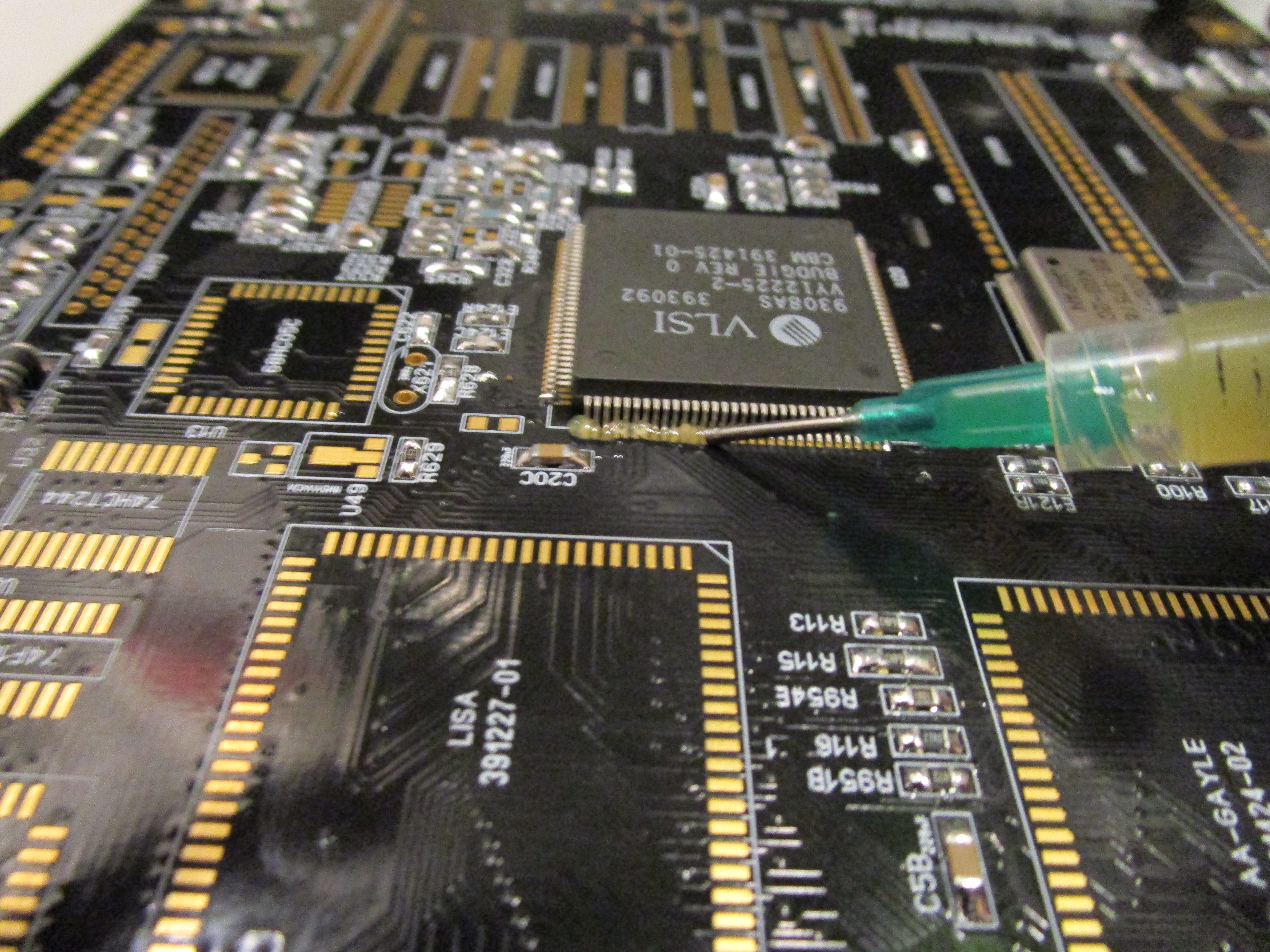
First I put the budgie on the pads, I do a SMALL solderblob on the corner. put the budgie in place, melt the solder so it stays there. and then on the opposite side of the budgie do the same thing. checking that ALL pins seems aligned as close to the middle of all pads. also pushing down the chip as much as possible to the pcb.
Add flux:
And start dragsoldering:
End result will be:
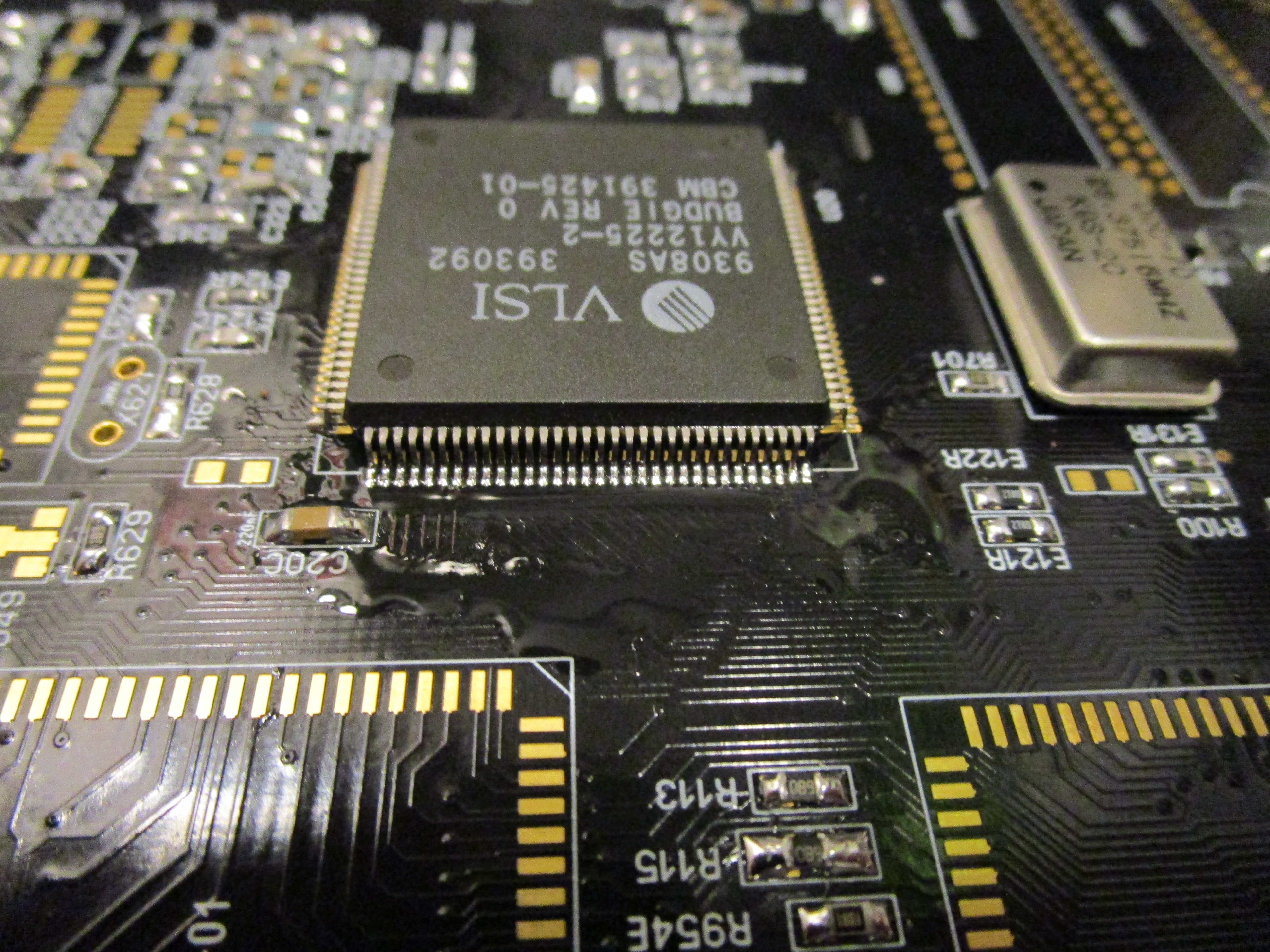
On E133R you should now have a buffered 28MHz signal from the budgie:

Now do LISA, Gayle and ALICE.
also add VGA and OR the RGB Connector for monitor (doesn’t matter what connector you do. I did both)

If you now power on your machine you SHOULD get a sync on the VGA/RGB:
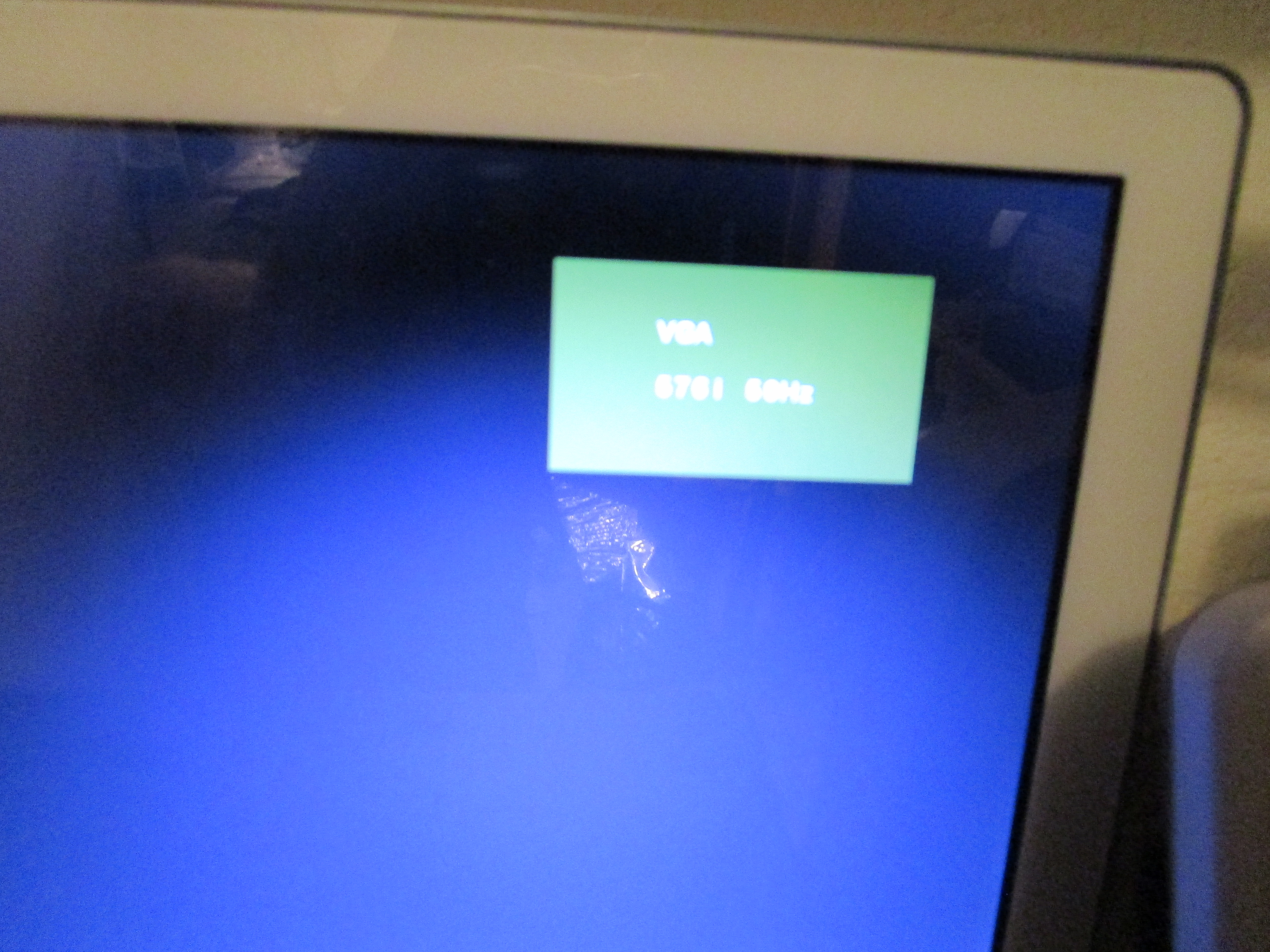
Not all monitors shows it. but mine does. you might notice it by screen go from pitch black to SOMEWHAT lighter picture.
you will NOT get any more picture or so. this is a sight that it SEEMS you have a working chipset etc.