Expansion Systems DataFlyer Plus 2.1
Way back in about 1992, I finally had enough money (ok, well, enough credit) to finally expand my Commodore Amiga 500 to how I wanted it. I previously had an A501 memory expansion module and an external floppy drive that my parents had bought me for Christmas the year or two before. A major upgrade was a Microbotics VXL*30 accelerator card which included a 68030 at 25mhz, and whopping 2MB RAM which was just amazing for the time. I may make a post in the future about the specifics of that card.
Enter the hard drive era…..
Besides upgrading the memory and processor, I also added on a hard drive expansion on the left hand side of the A500 case. This expansion was the Dataflyer 500. There were several different versions of the Dataflyer depending on the specific Amiga. It can be inserted as a card into the Amiga 2000, sidecar expansion like the 500, or completely separate box for the Amiga 1000. The PCB in all of them are very similar, with only minor changes in the chassis that held the individual card. There are also three different versions of the card: SCSI-only, IDE-only, or SCSI+IDE. Expansion Systems only populates the required components for each version. I seem to remember them being priced accordingly. I’m showing the SCSI-only version in this post.
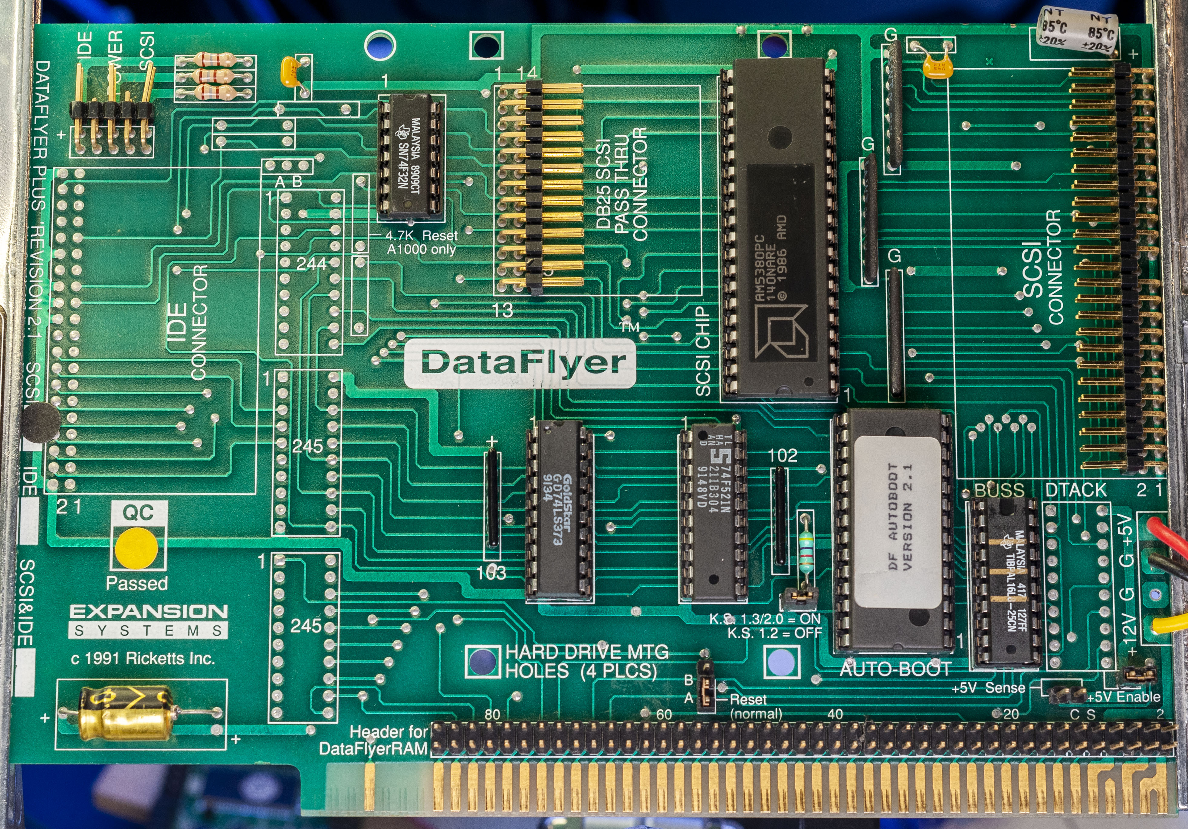
Front populated card
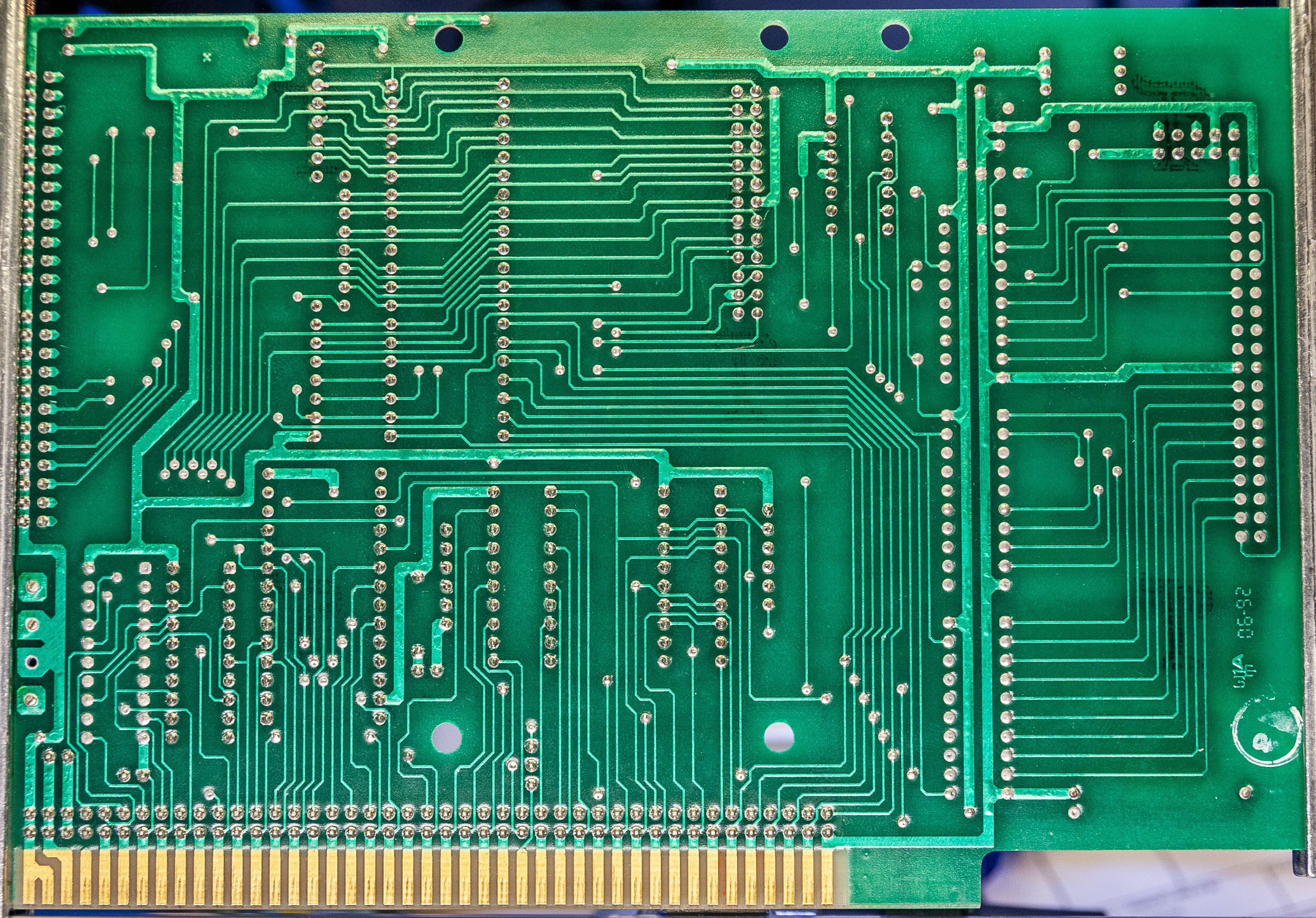
Back
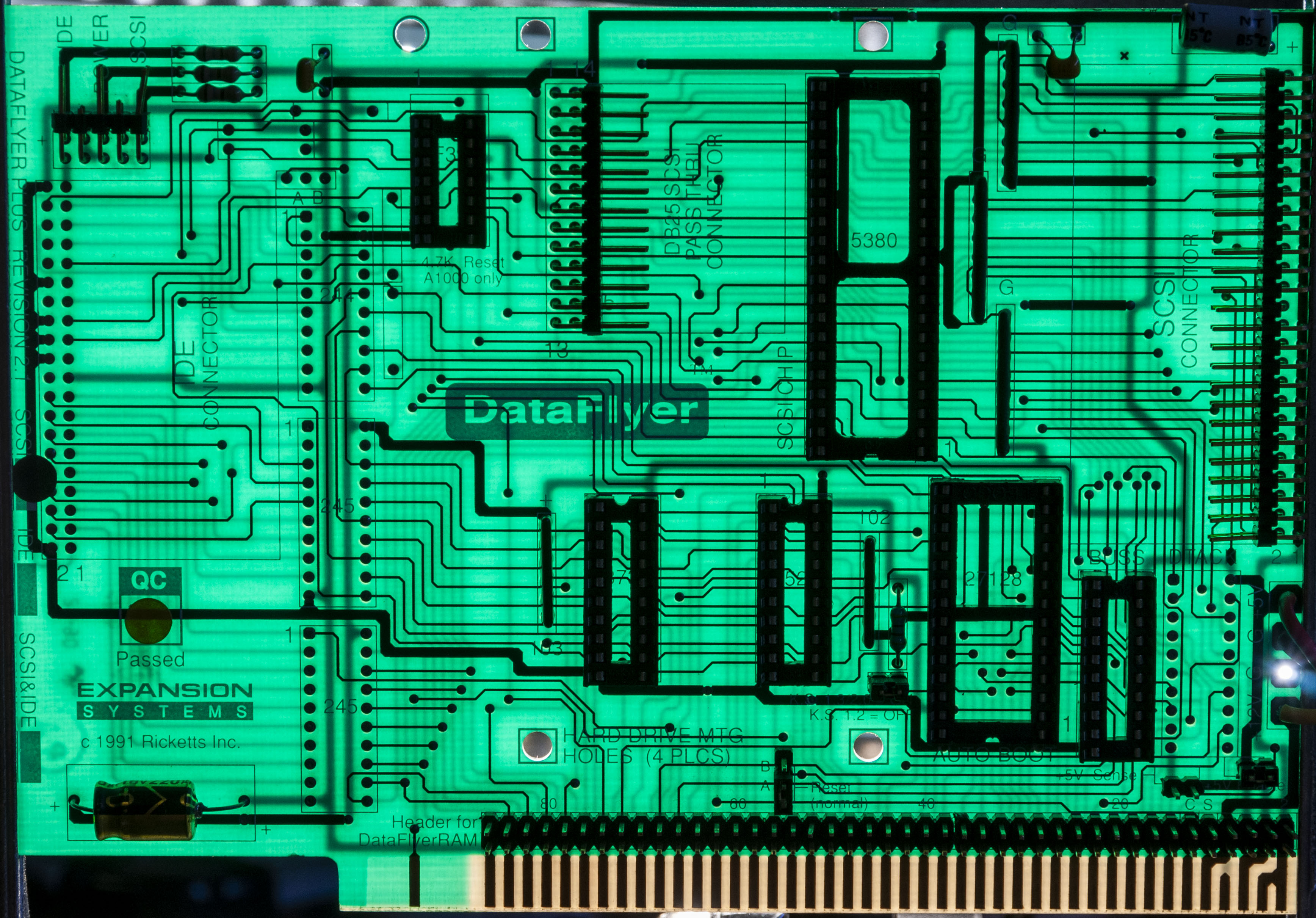
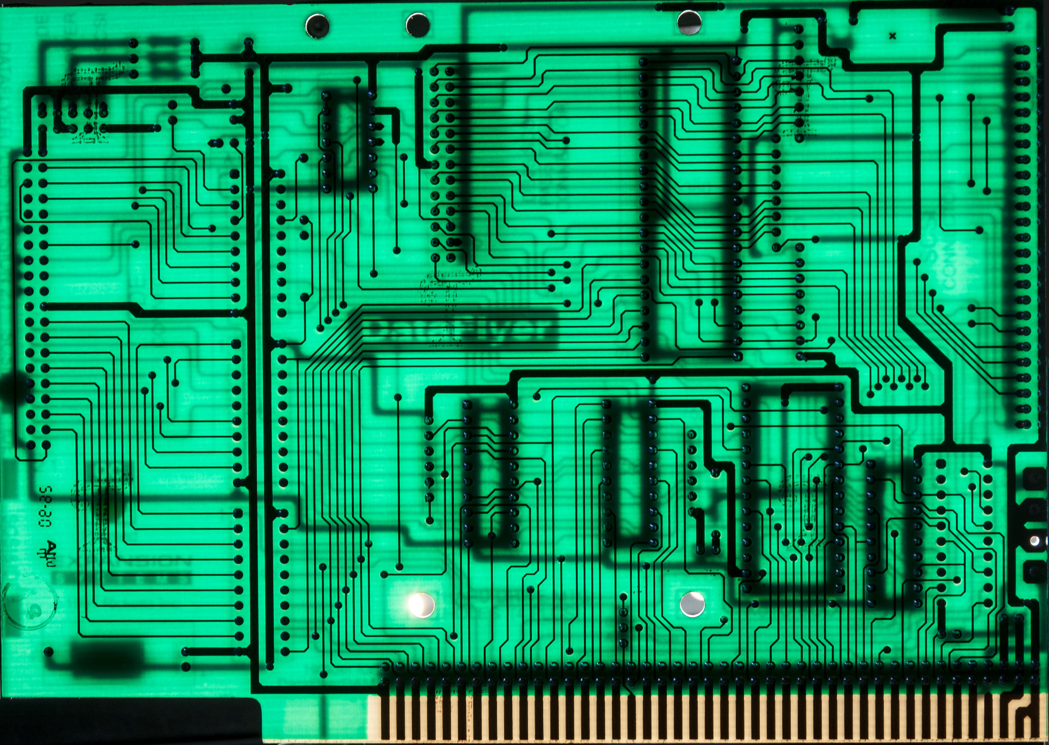
While I was messing around with trying to properly light these cards for photographing them, I noticed that the cards were fairly translucent and displayed all of the traces very clearly through the FR-4. The purpose of this post was just to share these images.
I was really struck with how beautiful the cards were when I placed a bright light source direct behind them.
I also pulled the DF Autoboot ROM version 2.1 from the board and used by TL866A ROM reader to read the code. It matches other copies around, but I’m archiving it in case it’s needed in the future. I’ve been messing around in Ghidra to disassemble the code. I don’t have great results yet, but this Autoboot ROM sounds like it’s unique. The boot code is only just enough to read the contents of the hard disk, which then contains the actual full boot code in the RDB of the disk. I’m not sure if they did that to reduce the size of the ROM or what, but I’ll have more on this later.
There are upwards of ten different ICs populated, again, depending on version:
- SN74F32N, which is a quad 2-input OR gate, to support the A1000(or so says the silk screening)
- SN74LS244/245N, that function as bus drivers for the IDE connector
- 74LS373, an octal latch
- 74F521N, an 8-bit comparator
- The 27C256-15 ROM mentioned above
- Two PALs:
- 16L8 labeled BUSS
- 16L8 labeled DTACK
- AM5380PC, the AMD SCSI controller chip.
I’m also going to read those PALs that is populated just to play around. It’s a 16L8, which I believe means that it’s only combinatorial logic, no registers. So if I drive all 10-bits on the input, and capture the contents of the 8 output lines, I should be able to determine the various equations used for the internal logic.
Lately, I’ve gotten the urge to reverse engineer some things, remembered my fascination with this card, and so I’m using this to have some fun. I think with these images, it would be trivial to put together a schematic for the card.
At least one user on an Amiga forum told me to essentially “not waste my time” and that the card is “not worth the effort” but for me, it’s part of my history. It was a crucial part of the computer I grew up on, and now that I have the time and ability to reflect back, and some more skills to understand how this thing works, I say why the f*ck not! This card is still operating after almost 30 years.
As always, I welcome comments and feedback on my posts.