Building a replacement Amiga 500 power supply
Intro
If you’re into retro computing, you probably know the Commodore Amiga 500—a beloved classic with surprisingly capable hardware for its time. But like many vintage systems, the original power supply is often a weak point after decades of use. Whether due to capacitor aging, unstable voltages, or just a general lack of confidence in crusty old electronics, replacing or upgrading the A500’s power supply is a common project. In this post, I walk through the path I took to build a modern replacement using a commercial off-the-shelf PSU, plus a few custom touches to ensure everything runs within spec.
Original A500 Power Supply
While I’ve been trying to get this new PCB working, I started observing really high and really low voltages present on the 68K’s VCC line. I disassembled an original, 35(?) year old power supply, and it looked pretty crusty to me. See below. The model number is Model 312503-01 DSP-A500 and the specs are:
+5V 4.50A
+12V 1.00A
-12V 0.10A
There are at least a few different variants made in a few different countries, so YMMV. Not all seem to be documented fully in one place.
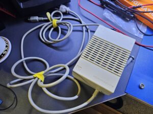
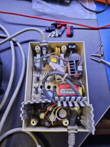
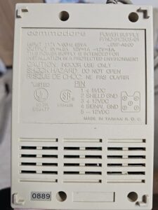
Now, I could “simply” recap the power supply, but there’s some tight physical access issues, and the single-sided circuit board is just ugly. Even if recapped, there’s no guarantee that even the original specs were that good.
The Amiga 500, which uses a weird 5-pin square DIN looking connector, uses three voltages +5v, +12v, and -12v.
An awesome Amiga Power Supply Guide is here: https://www.ianstedman.co.uk/amiga-power-supply-guide/
You can see a previous related posts where I powered the Amiga with a bench power supply. And another one here https://www.techtravels.org/2015/02/trying-to-use-mini-box-picopsu-120-to-power-amiga-but-12v-rail-is-out-of-atx-compliance/
The good news is that I bought a dozen of these solder-based connectors years ago whenever there was some type of kickstarter offering. They are still available online.
I explored several off-the-shelf power supply options that can be used, and found a few viable choices worth considering:
- The 50-watt Meanwell RT-50B closed frame power supply. It’s in a metal perforated chassis. Don’t think that the RT-50C is a newer, better version. It’s a different product entirely! Post 2019-versions should not require power resistors, below.
- The 50-watt Meanwell GP50A13D-R1B which is a desktop power supply. I incorporated an IEC320 in-line power switch which is pretty handy.
- The 120-watt PicoPSU PicoPSU-120 + 130W Adapter Power Kit bundled together with an ATX power supply break out board. This is WAY over spec’d and easily supports this application.
On which option to choose…
While the application I’m describing below uses the Meanwell GP50A, I’m not necessarily advocating for it. I wanted to share what I’ve done, what I’ve tried, and let you decide for yourself what suits your fancy. One isn’t necessarily better than the other as there are pros/cons/tradeoffs with each.
I have to admit that simply dealing with this PSU limitation described below makes the solution less cleaner, so if this bugs you, then maybe the RT-50B is a better choice for you. Keep in mind that I don’t love the internals of the RT-50B just hanging out either, to collect dust, be touched by kids, etc. You either have the heatsink block exposed with 12v, or the whole supply, with 120v mains level voltages exposed.
There’s also the static idle power draw and heat generation that adding the power resistors brings.
Building a case or reusing the existing one would likely solve all of these problems.
Building a replacement supply using the Meanwell GP50A
I’ve outfitted both the power supply and the 5-pin din connector with Anderson PowerPole connectors, which are very popular in the Ham Radio market. You can read more about them here.
These connectors work very well, have contacts which are easily crimped with reasonably priced crimping tools, connectors easily available on Amazon. I prefer the brand name, as with most things I buy, but finding those on Amazon is harder, with slower shipping options. I like PowerWerx for everything related!
Power Rangers Resistors (required for certain supplies)
One thing that I failed to realize when I first started looking into this was the fact that the voltage tolerance, line+load regulation specifications only applies when in the specified current range.
What this means is that for the 12v and -12v rails, the voltage at lower current draws will not be guaranteed. At idle my fairly stock A500 only draws about 20ma on the 12v and -12v rails. This means that these will be potentially affected. I’d like to do some testing to characterize the real-world performance of this application without power resistors. The idle draws are definitely under the minimums, but I’d like to see first-hand what the real effects are. It’s very possible, fwiw, that these aren’t strictly necessary!
Thanks to “William from Norway” for pointing this need in the power supply guide linked above.
My solution was to order some power resistors through digi-key:
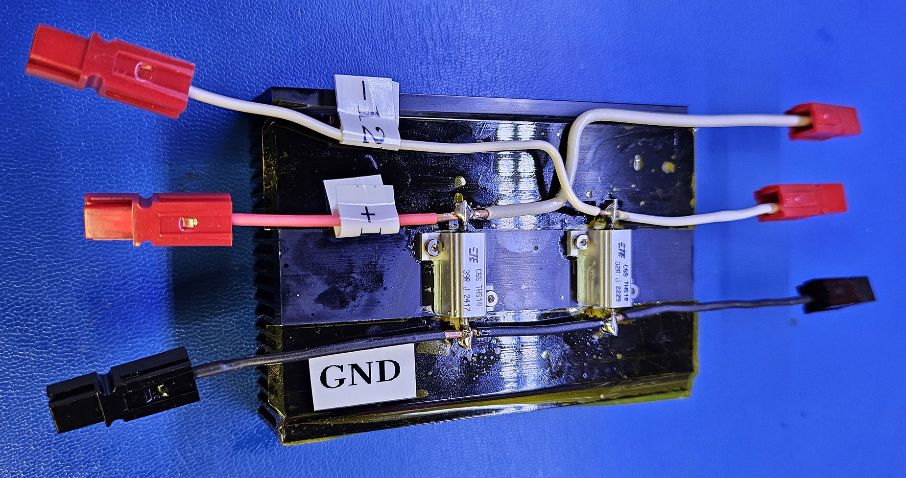
To ensure stable voltage regulation from the Mean Well GP50A power supply, we added minimum load resistors on the +12V and -12V rails. This supply requires at least 0.3A on +12V and 0.1A on -12V to stay within spec. We calculated suitable resistor values using Ohm’s law: for +12V, a 39-ohm resistor draws ~0.31A (12V ÷ 39Ω), and for -12V, an 82-ohm resistor draws ~0.146A—safely above the minimums. These resistors dissipate 3.7W and 1.75W respectively, so they must be mounted on a heatsink to prevent overheating. We used aluminum-housed chassis-mount resistors bolted directly to the heatsink with thermal paste for efficient heat transfer.
There’s a tradeoff in choosing these values: while larger resistors would waste less power, they might not draw enough current to keep the supply within its regulation range. Choosing the minimum resistor values that just meet the load requirement minimizes unnecessary static power draw and heat, while still ensuring reliable operation. In this setup, we prioritized long-term stability and compliance with the PSU’s design limits, accepting a few extra watts of dissipation as a fair trade for cleaner, spec-compliant output voltages.
My power resistor block
I’m proud of this little thing I built this weekend. It features:
- a 100mm x 70mm x 25mm aluminum black anodized heatsink
- M2 tapped holes for secure attachment of the resistors
- TE chassis mount resistors linked above
- Arctic Ice thermal compound
- 3M 5413 polyimide tape to ensure insulation from the heatsink
- Heavy gauge wire for the +12v rail. 14AWG. Yes, probably overkill.
- Anderson PowerPole connectors for plug’n’play
What’s the net effect?
The resistor block did exactly what I needed—it brought the voltages back in line. The +12V rail dropped from 13.25V down to a solid 12.36V, and the -12V rail came down from -12.5V to -11.84V. According to the GP50A datasheet, the ±12V rails are allowed to vary by ±5% under load, and with the resistors in place, both rails are now well within that range. No more floating outputs, and everything’s stable and spec-compliant. Solid results, but it was a pain in the butt.
The temperatures this setup achieves is really impressive. Without a heatsink, these resistors runaway to 200F and beyond. I didn’t want to see how high it could go. With the heatsink, I’m seeing comfy temps down near 100F stable over time.
Final Solution
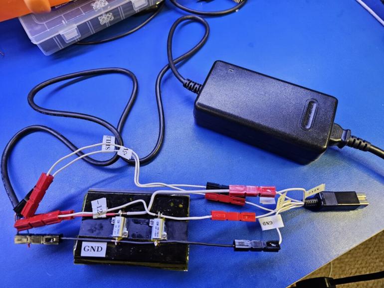
The jury is still out on whether this was the “best” solution or even an ideal one. It works, the voltages are all within tolerances, which is really what I care about. It’s not a clean-cut off the shelf product. I realize you can simply go buy one. I learned a bit and enjoy solving problems myself. This is just revision one.
Because I have the Anderson PowerPole connectors in place, what I can do now is simply build another one, disconnect the 5-pin DIN, and attach it. I mixed feelings about these connectors. They are bulky, separate, and just large. I wonder if a more compact 5-pin connector like a Molex or similar doesn’t make more sense. I do love the modularity of it.
Summary
This wasn’t a drop-in replacement or a plug-and-play solution—but it works, it’s safe, and it’s solid. The voltages are regulated, the PSU is spec-compliant, and I learned a lot in the process. While there are cleaner or more compact solutions out there, this modular approach gives me flexibility for future revisions. I can always swap in another supply thanks to the standardized connectors. Is it perfect? Nope. But it’s mine, it’s functional, and it solved a real problem. That’s a win in my book.
The post Building a replacement Amiga 500 power supply appeared first on techtravels.org.


