From Flux to Filenames: 335ms Inside Paula
Amiga · Paula 8364R7 · logic analyzer
One real floppy read on a PAL Amiga, captured at Paula’s inputs and outputs. The
drive’s flux pulses and control writes go in. Direct memory access (DMA) requests and bus words come
out. Recognizable filesystem names emerge at the end.
You type dir on an Amiga and press Return. To produce the directory listing, the Amiga reads
directory data from disk. We’ll use a logic analyzer connected to a running Amiga to follow that read
from start to finish. The analyzer records the signals entering Paula and the DMA requests and bus words
leaving it. Where no pin exposes the intermediate state, my earlier functional analysis of the reconstructed circuitry explains
what happens inside Paula. Then we’ll decode the captured words. If we truly understand the read path,
they will become sectors with valid checksums and recognizable filesystem names.
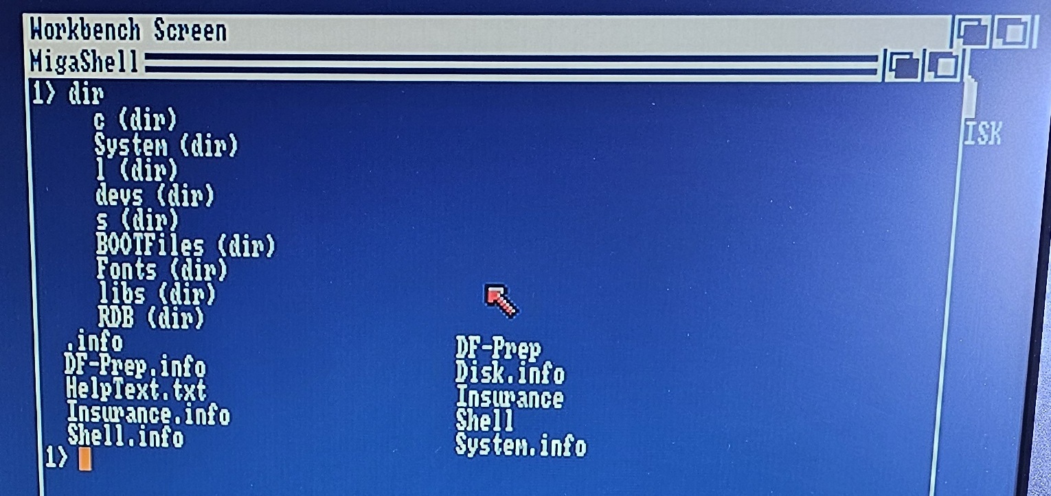 alt="An Amiga Shell window showing the output of a dir command, listing directories c, System, l, devs, s, BOOTFiles, Fonts, libs and RDB, and files including .info, DF-Prep, DF-Prep.info, HelpText.txt, Insurance.info, Shell.info, Disk.info, Insurance, Shell and System.info">
captured signals around Paula.
That method combines two sources of evidence.
The first is the capture. I put a logic analyzer on a running PAL Amiga and probed the
chip data bus, the register address bus, the DMA request line, the interrupt lines, the color clock, and
Paula’s three floppy pins. Then I recorded a complete floppy read and the start of the next with Workbench
up and a dir running. The recording places flux pulses, register traffic, requests, bus words,
and interrupts on one timeline.
The second is the functional model. Other researchers decapped and photographed Paula,
produced the vectorized die trace, and worked out rough schematics of its circuit blocks. Starting from
their work, I analyzed what those blocks do and how they operate together as a complete floppy controller.
That functional model explains what happens inside Paula between the events visible on its pins.
 alt="Cover of Inside Paula's Floppy Controller, Part I: Functional Analysis of the MOS 8364R7, by Keith Monahan, showing the vectorized die of the 8364R7 with its 1984 CBM and 8364R7 markings">
If you crave the internals
Inside
Paula’s Floppy Controller, Part I
The complete functional analysis is a paper of its own. This post borrows only the details needed to
explain what the analyzer sees at Paula’s boundaries.
The capture and functional model together make a prediction at each boundary. The observed input and recovered
logic say what should appear next. The next captured boundary confirms that prediction.
In the steps below, the dark panels present captured values, model predictions, and results reconstructed
from the capture; each panel header identifies its role. Where a step names a region of the chip, it carries
a small tag like 10c next to the title. The tag identifies the corresponding
module in the paper linked above, where its circuitry and function are described in detail.
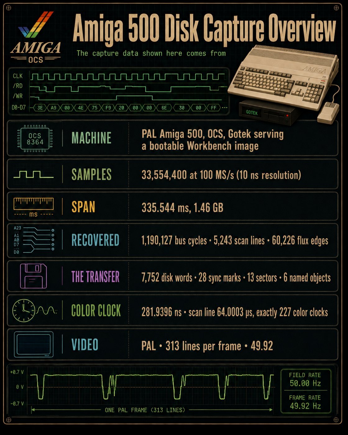 alt="Infographic titled Amiga 500 Disk Capture Overview summarizing the PAL Amiga 500 and Gotek, 33,554,400 samples at 100 million samples per second spanning 335.544 milliseconds, and the recovered bus cycles, scan lines, flux edges, disk words, sync marks, and sectors">
How we watched Paula
The proof depends on observing many signals on one timebase.
An oscilloscope shows analog behavior such as voltage levels, rise and fall times, overshoot,
undershoot, and ringing. A logic analyzer compares each input with a voltage threshold and records the
result as a zero or a one. That digital representation lets it record dozens of signals together across
millions of time aligned samples, covering the entire read while retaining enough timing detail to resolve
individual pulses and bus cycles.
For this capture, the analyzer records every channel once every 10 nanoseconds across 335.544
milliseconds. The resulting buffer preserves the register setup, the complete disk read, and the start of
the next read on one timeline.
This article reports custom register addresses as byte offsets. The captured RGA bus contains address
bits 8 through 1, so raw code $04 shifts left one bit and appears here as byte offset
$008.
The analyzer produces a file of raw digital levels. Every measured result in this
post starts here:
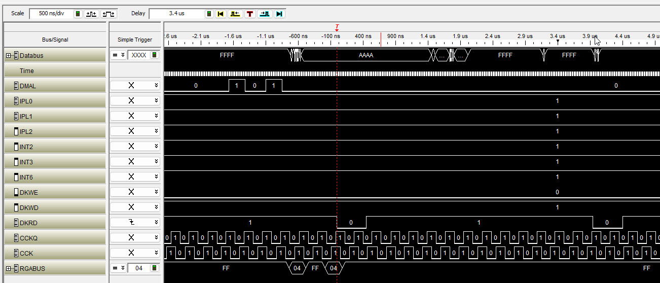 alt="A logic analyzer waveform window at 500 nanoseconds per division showing the data bus stepping through FFFF and AAAA, two narrow positive pulses on DMAL, transitions on DKRD, square waves on CCK and CCKQ, and the register address bus showing FF and 04">
visible. The two narrow pulses on DMAL are Paula asking for memory cycles. CCK and
CCKQ are the color clock and its quadrature partner, ticking away underneath everything.
RGABUS stepping from FF to 04 identifies a disk DMA cycle,
and the data bus goes to AAAA as the word crosses. The remaining steps follow events like
these into recovered words and names.
Where the probes went
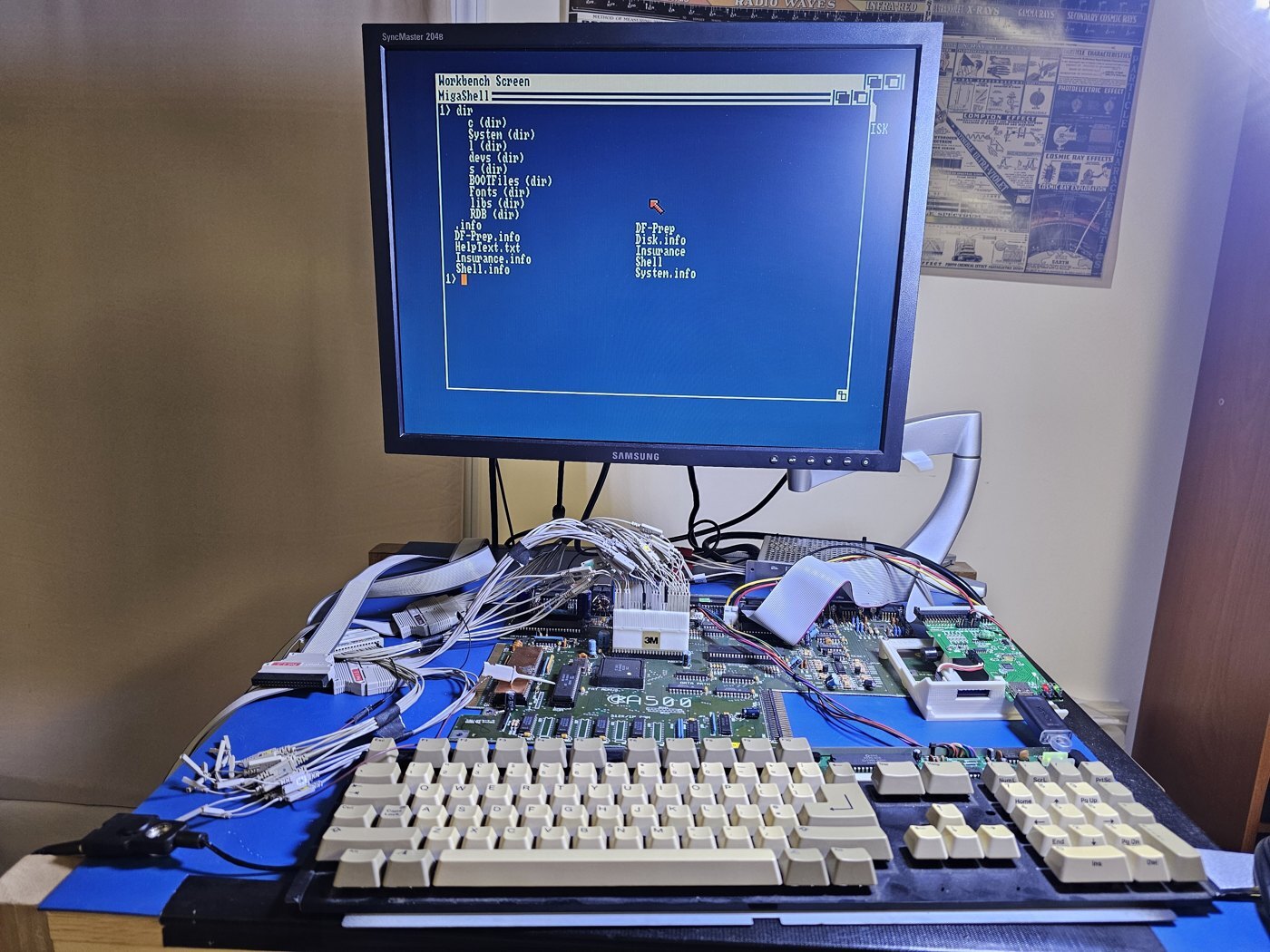 alt="A bare Amiga 500 motherboard on a blue antistatic mat, with logic analyzer leads concentrated around Paula and a monitor showing a Workbench Shell">
probes attach to the DIP clip over Paula, the Gotek is attached at the drive interface, and the Shell
is visible on the monitor.
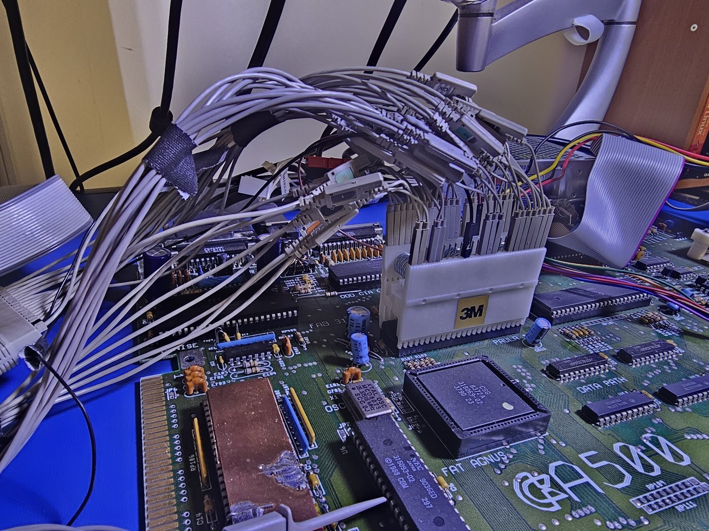 alt="Closeup of a 3M DIP clip fitted over Paula on an Amiga 500 motherboard, with individual logic analyzer probes attached to its contacts">
to its contacts. Together they capture the data bus, RGA lines, clocks, DMA request, interrupt lines,
and floppy signals. A separate lead provides ground from nearby.
This capture uses a PAL Amiga 500 motherboard running Workbench and a Gotek loaded with the disk’s
.adf image so the same track can be presented again on demand. Most analyzer probes attach individually to contacts on the
DIP clip over Paula, where the data bus, RGA lines, timing signals, DMA request, interrupt lines, and
floppy signals are all available. A separate nearby connection supplies ground. One capture and one
timebase cover both ends of the transfer.
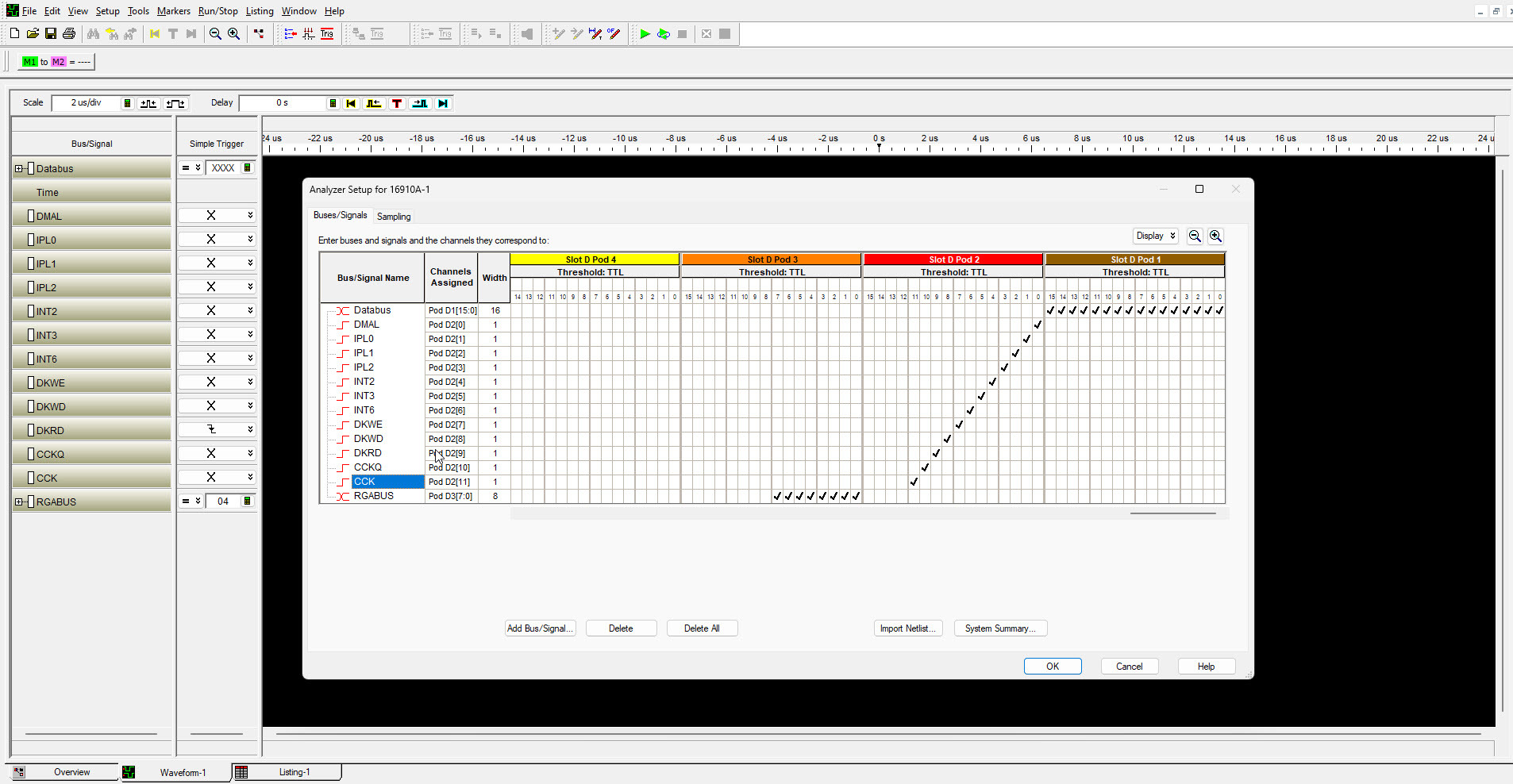 alt="The analyzer setup dialog listing each bus and signal against the pod and channel it is wired to: Databus on pod D1 bits 15 to 0, then DMAL, IPL0 to IPL2, INT2, INT3, INT6, DKWE, DKWD, DKRD, CCKQ and CCK on pod D2, and RGABUS on pod D3">
physical probe.
Each signal answers a specific question.
here.
cycle by putting a register address on these eight lines. The value distinguishes screen fetches,
disk words, blitter cycles, and CPU writes. This post shows decoded custom register offsets, so the
raw RGA code
$04 appears as disk register $008.event on the chip timing grid and on the elapsed timeline.
This is the closest captured signal to the pattern stored on the disk.
timing of each pulse predicts a later bus grant.
pins. Their value shows when an interrupt reaches the processor.
The analysis rebuilds the color clock grid from those channels, numbers every scan line and DMA
slot, and turns register addresses into cycle names. The analysis software recovers bit cells from the
flux, allowing each word on the chip bus to be traced back to the transitions that produced it.
Disk vocabulary
reports each one as a short pulse.
represents one value and an empty cell another. Recovering the cell boundaries is the first decoding
job.
transitions arrive two, three, or four cells apart.
memory write while the CPU handles other work.
take turns using it.
one of these.
Inputs to Paula
Two independent inputs define the read: flux pulses already arriving from the drive, and bus writes
that tell Paula when to start grouping them into words.
-
STEP1
The Shell asks the filesystem for the directory
dirasks the filesystem to walk the current directory, and the filesystem requests the
disk blocks that describe it. That request supplies the real disk read this story follows. -
STEP2
The directory request requires a track read
trackdisk.devicekeeps data
from a previously read track in a memory buffer. If the requested track is already there, it can
supply the sector without another disk transfer. In this capture, the requested track is absent, so
the system asks the drive for it and reads the resulting data through Paula into chip RAM. That is
the disk transfer traced in the remaining steps. -
STEP3
The Amiga selects a track through the drive interface
One of the two Complex Interface Adapter (CIA) chips asserts the drive select, side, motor, and step
control lines; the other reads drive status such as track zero, write protect, ready, and disk change.
The Gotek electrically appears to the Amiga exactly as a floppy drive does. It receives those
same control lines and returns the same status and read data signals. From the mounted.adf
disk image, it supplies the track and side selected by the Amiga. Paula sees the resulting read pulses
onDKRD. That pin is Paula’s entire view of the drive’s read stream. -
STEP4
The read pulse stream is already reaching Paula 10c
The Gotek presents the selected track as low pulses on
DKRD, with each pulse representing
a flux reversal in the disk image. Those pulses arrive before software arms the transfer. Arming chooses
where Paula begins collecting the already flowing stream into words.The interval between successive pulses carries the data. This interval is often called delta t,
writtenΔt. A transition becomes a one in the recovered cell stream, and each empty cell
before the next transition becomes a zero.DKRD, Paula pin 37captured inputfalling edge one pulse one detected flux reversal cell period about 2 µs the timing unit Paula recovers delta t between edges about 4, 6 or 8 µs 2, 3 or 4 recovered cells About 4 µs contributes
10, 6 µs contributes
100, and 8 µs contributes1000. Joining those groups reconstructs the raw
MFM cell stream. Longer gaps occur outside the valid sector contents, including the track gap. -
STEP5
Software configures the destination and arms Paula 10p 10i
Before a disk word crosses the bus, the CPU supplies the destination, prepares the completion
interrupt, and writes the transfer length twice.writes that configure this readcaptured register writes1 DSKPTH $020 $0000 destination high half 2 DSKPTL $022 $6B14 destination $006B14 in chip RAM 3 INTREQ $09C $1002 clear a stale disk interrupt 4 INTENA $09A $8002 enable the block complete interrupt 5 DSKLEN $024 $9CBE set enable, read, and 7,358 words 6 DSKLEN $024 $9CBE the second write arms the transfer Agnus owns the destination pointer and supplies every bus cycle and RAM address.
Paula supplies requests and disk words. The length covers more than one complete track, so the read can begin
anywhere in the track stream without ending before every sector has been presented.Why write the length register twice? The Amiga
Hardware Reference Manual specifies this sequence. The write strobe is registered one stage
earlier than the enable bit. On the first write, the sequencer sees the strobe before enable. On the
second, enable is visible and the sequencer arms.what the arming instant predictsmodel prediction, confirmed laterAligning the captured bus words with the
recovered cells places the first word boundary at the secondDSKLENwrite. That
arming instant therefore establishes how Paula groups the already flowing stream into 16 bit
words. No captured write sets the word sync enable inADKCON, so word sync is
disabled for this read and the sync marks should cut across DMA words at
a stable phase. The later sync scan and the software shift provide the confirmation.
From pulses to words
Five internal transformations are enough to predict the raw words Paula will present to Agnus.
-
STEP6
Each
DKRDpulse becomes one internal event 10dA Schmitt trigger cleans the external pulse, and synchronizing latches bring it into Paula’s clock
domain. The resulting internal level lasts for more than one clock. Paula reduces that active level
to one event per flux reversal.This is standard clock domain crossing practice. Successive
clocked storage stages give an edge that arrives near a clock boundary time to settle before the rest
of the circuit uses it. A modern block diagram often shows this as two flip flops back to back. Paula
reaches the same functional result with latches and surrounding gating.The synchronized path provides the current level and a copy delayed by one clock. A single gate
combines them:event = current level AND NOT(previous level) AND enabled
The expression is true for one clock after the internal level rises. Each pulse therefore becomes
one event, regardless of how long the pulse remains active. -
STEP7
The DPLL recovers the embedded cell clock 10j 10k 10s 10t
The floppy interface carries no separate clock signal; one wire delivers one pulse stream. The clock is
embedded in that stream instead. MFM interleaves clock cells with data cells, so the stream carries
its own timing and guarantees another transition within four cells. Paula recovers that timing to
decide which cells contain transitions and which are empty.A DPLL is a digital phase locked loop. A PLL compares the phase of incoming transitions with a local
timing reference and continuously adjusts that reference to stay locked.In Paula, an early or late event corrects the phase, while a repeated bias corrects the estimated
cell rate. The result is one bit decision for every cell, including cells with no transition. -
STEP8
Paula copies sixteen raw MFM cells into one word 10q 10r 10h
The disk data sent over the bus is still raw MFM. On each recovered cell boundary, Paula shifts the
cell value into the receive register: one for a transition and zero for an empty cell. After 16 cells,
the register holds one 16 bit Amiga word.Those 16 raw MFM bits do not represent 16 bits of usable file data. They still contain MFM clock bits,
and the AmigaDOS data remains separated into odd and even halves. Software realigns and decodes the raw
words in steps 16 and 17.Starting from the arming point in step 5, each successive group of 16 recovered cells therefore
predicts the next raw word in the captured bus stream. -
STEP9
Sector sync preserves the existing word phase 10q 10r 10e
Each sector begins with two
$4489sync marks. A missing clock bit makes that pattern
illegal in ordinary MFM data, so it can identify a sector boundary from any starting position in the
stream.The first read contains 13 sector starts, so it should contain 26 sync marks in 13 pairs. The
recovered stream contains all 26 at one stable position within the DMA words. Paula keeps the word
phase established at arming.$4489 in the recovered cellsreconstructed from captured fluxsector starts 13 one pair at each start sync marks 26 all 13 expected pairs found whole DMA words 0 every mark straddles two words position within DMA word cell offset 6 zero-based from the left, or MSB, side The word sync feature is switched off for this read. Here,
cell offset 6 means the seventh cell from the left, counting from zero at the MSB side
of the captured word. It is a serial-stream position, not conventional hardware bit 6; in conventional
numbering, the sync begins at bit 9. Paula’s framing remains fixed to the arming instant from step 5,
so every sync mark begins after six earlier cells, leaving ten cells in that word and six in the next.
Step 16 shows the exact fit. -
STEP10
Finished words wait in a three stage queue 10l 10g
Recovered cells arrive continuously, while Agnus provides three fixed disk slots during each scan
line. Paula holds each completed word until the next available slot.The silicon reveals three 16 bit data stages and three matching valid bits. The capture shows their
externally visible result:what queueing changespredicted external behaviorusual delivery 2 words during one scan line catch up delivery 3 words when arrival phase requires the third slot word value and order unchanged delivery time moves The queue delays delivery while preserving word value and order.
The next part follows the preserved value and order onto the chip bus.Each valid bit travels with its data word. Queue occupancy therefore predicts Paula’s external
DMALrequests.
Paula talks to the system
The capture can now show each external boundary: request, grant, memory write, and completion.
-
STEP11
Paula asks Agnus for a slot 10g
Agnus controls memory addressing and the register address lines. When a word needs moving, Paula
requests a bus slot throughDMAL.DMALcarries a fixed 16 slot serial frame at the start of each scan line, one bit per
color clock from$00through$0F. The Hardware Reference Manual names the pin’s
audio and disk DMA request function, but does not spell out this format. The recovered circuit and the
capture show how it works: the first two slots are zero, the next six describe disk DMA, and the final
eight carry two bits for each of the four audio channels.The six disk bits are transmitted consecutively as three direction and request pairs, one pair for
each queue stage. Disk bit 1, in slot$02, gives stage A’s transfer direction; bit 2, in
$03, requests its bus transfer. Bits 3 and 4 do the same for stage B in slots
$04and$05, followed by bits 5 and 6 for stage C in$06and
$07. During a read, every direction bit is zero and a request bit is one when its stage
contains a word for Agnus.Figure 1. Each request predicts its grant. Paula has two words waiting, so
it uses the later two request positions. Four color clocks after each request, Agnus puts
raw code$04on RGA, decoded as disk cycle$008, and the corresponding word
crosses the bus.
The DMAL frame format. The highlighted read line has words waiting
in queue stages B and C, so its six disk bits are000101. Slots$05and
$07therefore carry the two requests shown in Figure 1.
DMAL request to Agnus grantcaptured result, whole captureserial frame 16 bits one position encoded bit per color clock disk field slots $02 through $07 direction and request for stages A, B and C request to grant 4 color clocks 7,752 of 7,752. Zero exceptions. request positions $03 $05 $07 granting $07 $09 $0B words waiting 1, 2 or 3 last request, last two, or all three The number of request positions used on a line is the number of words Paula
wants moved. The queue packs toward the output stage: one pending word uses only the last
position, two words use the last two, and three use all three. Queue occupancy predicts
the requests, and every request predicts its bus grant. DMAL carries no address field. Agnus
identifies the requested transfer from the bit’s position in the frame, then grants the corresponding
bus slot four color clocks later. -
STEP12
Agnus grants the request and the word crosses the chip bus
Agnus owns the memory bus and the address generator. On the granted cycle the register address bus carries
raw code$04, decoded here as register offset$008, while Paula drives its
word onto the shared data bus. Agnus writes the word to the pointer address and advances that pointer
by two bytes.The three disk slots sit together near the start of each scan line. A word that finishes after the
last slot waits for the next line, while a word already waiting can leave immediately. The queue
absorbs that variable delay while preserving the word value and order. -
STEP13
One captured word connects flux to RAM
word #112 · six flux transitions · one bus word · one RAM address
Let’s use word 112 as a concrete example because it lets us check every stage just described
against the same piece of captured data. Word numbering counts from zero at the first delivered
word, so word 112 lands 224 bytes past the programmed destination of$006B14, at
$006BF4. Its six flux transitions become one 16 bit word, Paula
places that word on the bus, and Agnus writes it to that known RAM address. Word 112 also contains
the beginning of the first sector sync, so we can follow the same bits into the alignment work
in Step 16.Figure 2. Word #112, from six pin transitions to one address in RAM. The
six falling edges are spaced 2, 2, 3, 4, and 3 recovered cells apart, which puts
transitions in cells 0, 2, 4, 7, 11, and 14. Those cells predict$A912. Paula put
$A912on the bus, and Agnus wrote it to$006BF4. The value predicted from the
input matches both observed outputs.
The first
$4489sync mark is split across words 112 and 113. The second
spans words 113 and 114.101010010001001000100101000100100010010101010100word #112 $A912 → $006BF4word #113 $2512 → $006BF6word #114 $2554 → $006BF8Figure 3. Two sync marks across DMA word boundaries. The amber run is the
first$4489. The blue run is the second, sixteen cells later. Both begin at
cell offset 6, the seventh cell from the left, or MSB, side, and finish with the first
six cells of the next word. That phase matches all 26 marks in the first read. Step 16 will apply the
complementary shift.
-
STEP14
The same chain repeats across the entire read
first read · 7,357 words
The request, grant, bus, and memory sequence repeats for every word. Agnus advances from the
programmed destination in consecutive two byte steps. The CPU leaves every disk register untouched,
confirming that Paula and Agnus carry the transfer forward without software feeding them each word.
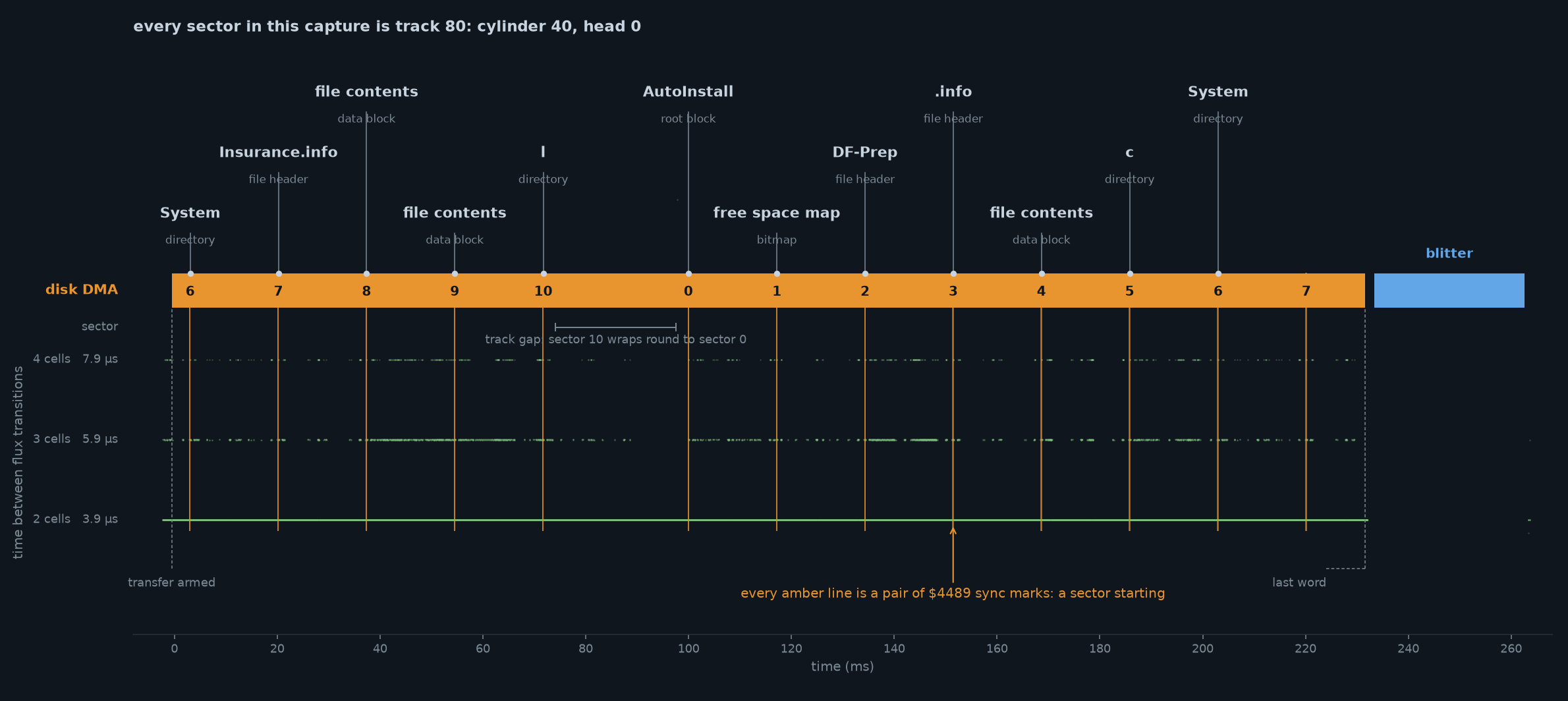 alt="A single timeline of the read, headed every sector in this capture is track 80, cylinder 40, head 0. Faint green rows plot the time between flux transitions at 2, 3 and 4 cells. Amber vertical lines mark each pair of $4489 sync marks. The disk DMA bar carries the sector number at each one, running 6, 7, 8, 9, 10, then 0, 1, 2, 3, 4, 5, 6, 7, with a bracket marking the track gap where sector 10 wraps to sector 0. Callouts name each recovered block.">
Figure 4. The whole read on one axis. Every sector is on track 80. The read begins
at sector 6, continues through sector 10, crosses the track gap to sector 0, and continues to sector
7. Green rows show the captured flux spacing, amber lines mark the sector sync pairs, and labels
identify the recovered blocks. The blue bar marks the alignment pass in step 16. The shared axis
connects flux spacing, sector order, and decoded blocks.
-
STEP15
The counter runs out and the interrupt fires
Paula counts down from the programmed length. When the count expires, the transfer sequencer stops
accepting new words, drains the queue, and then raises the block complete interrupt.Figure 5. The sequencer predicts completion order. The second length write arms the
sequencer. With word sync disabled, this read enters RUNNING immediately. Reaching zero stops new
words. DRAINING releases the final queued word before the interrupt appears.
end of transfercaptured order1 disk word $AAAA the final queued word crosses 2 IPL → 1 block complete reaches the CPU 3 INTREQR $01E $0042 the handler sees the disk bit; bit 6 is an unrelated pending blitter request 4 INTREQ $09C $0002 the handler acknowledges it 5 DSKLEN $024 $4000 software stops the engine The final word crosses before the interrupt appears. The observed
order confirms that queue drainage controls completion after the count expires.one word shortcaptured count: 7,358 asked, 7,357 deliveredThe length register programmed 7,358 words. This session put 7,357 on the bus. On the same page
as the double write rule, the manual warns: “the last word in a disk read DMA
operation may not come in, that is, one less word may be read than you asked for.” The capture
shows exactly that.The continuity evidence places the missing word at the end. All 7,357 delivered words lock to the flux
at one fixed offset and a constant 16 cell stride. Their destination addresses form one continuous
range from the programmed pointer. After the final word, Paula stops requesting and every disk slot
remains idle while the length register still holds its armed value.
Proving the interpretation
Raw disk words are sitting in memory. If the interpretation is right, they will align, decode, and become
valid filesystem contents. The partial second read then checks the word phase produced by a new arming
instant.
-
STEP16
The blitter aligns the sectors and rejoins their data bits
Chip RAM now contains the raw MFM cells received by Paula. Two transformations remain. The sync pair
begins at cell offset 6 within a DMA word, so every sector field crosses the word boundaries in memory. Within
each sector, the Amiga sector format stores the odd bits of every original 32 bit value in one half and
the even bits in another. MFM clock cells occupy every other position in both halves. The captured blits
perform the alignment first and the odd and even merge later.the first blit after the readcaptured register writes1 BLTCON0 $040 $05CC enable B and D; copy B through the logic function 2 BLTCON1 $042 $A000 shift B right by 10 bits across successive words 3 source B $006BF0 begin with two words of lead in before the straddled sync 4 destination D $006B0E write the realigned stream to an earlier buffer 5 BLTSIZE $058 $15A0 86 rows of 32 words; this pass aligns 2,752 of the captured words The shifter treats successive source words as one continuous stream. Each output word receives the
final ten bits of the previous source word followed by the first six bits of the current word. Step 13
found the first sync after six earlier cells in source word$A912. Its remaining ten bits and
the first six bits of$2512therefore become one aligned$4489. The complementary
shift follows directly from the captured phase: six cells precede the sync, leaving ten sync bits in that
word for the shifter to carry into the high end of the aligned output.Figure 6. Alignment and decoding are separate blitter operations.
The first pass moves the straddled sync pair onto a word boundary. A later pass clears the alternating
MFM clock cells, shifts the odd bits into their original positions, and combines them with the even
bits. The lower panel uses values from sector 0, the block processed by the captured merge blit. They
produce its name length and the first three letters ofAutoInstall.
The second operation reverses the Amiga sector layout. Each original 32 bit value was separated into
an odd half and an even half before MFM encoding. The mask$55555555, binary
0101..., retains the data cell from each clock and data pair. The same mask applies to both
halves.$AAAAAAAAselects the clock cell positions, so it does not contribute to the decoded
value. Shifting the masked odd half left by one returns those bits to the odd positions. Combining that
result with the masked even half reconstructs the original value.the later odd and even mergecaptured register writes1 BLTCDAT $070 $5555 supply the repeating data cell mask 2 source A / B $00828F / $00848F read backward from two halves exactly $200 bytes apart; the software writes odd byte addresses, and the pointer registers have no bit 0, so the blitter reads the last word of each half 3 BLTCON0 $040 $1DD8 shift A by one and select alternating bits from A and B 4 BLTCON1 $042 $0002 descending mode makes the A shift move left 5 BLTSIZE $058 $0808 produce 256 words, or one 512 byte decoded block The
$D8logic function uses the alternating C mask as a
selector: positions where C is zero come from shifted A, and positions where C is one come from B.
A is the odd half and B is the even half. This performs the mask, shift, and combine across the block.
This recorded pass decodes track 80, sector 0. The lower panel uses odd and even values from that same
block. Their result,$0B Aut, is the eleven character length and beginning of the volume
nameAutoInstall.The first transformation predicts the aligned sync pair, and the second predicts the decoded bytes.
Both predictions match the captured blitter setup. The resulting checksums and filesystem structures in
the next step test the complete reconstruction. -
STEP17
The whole chain, from flux to filesystem
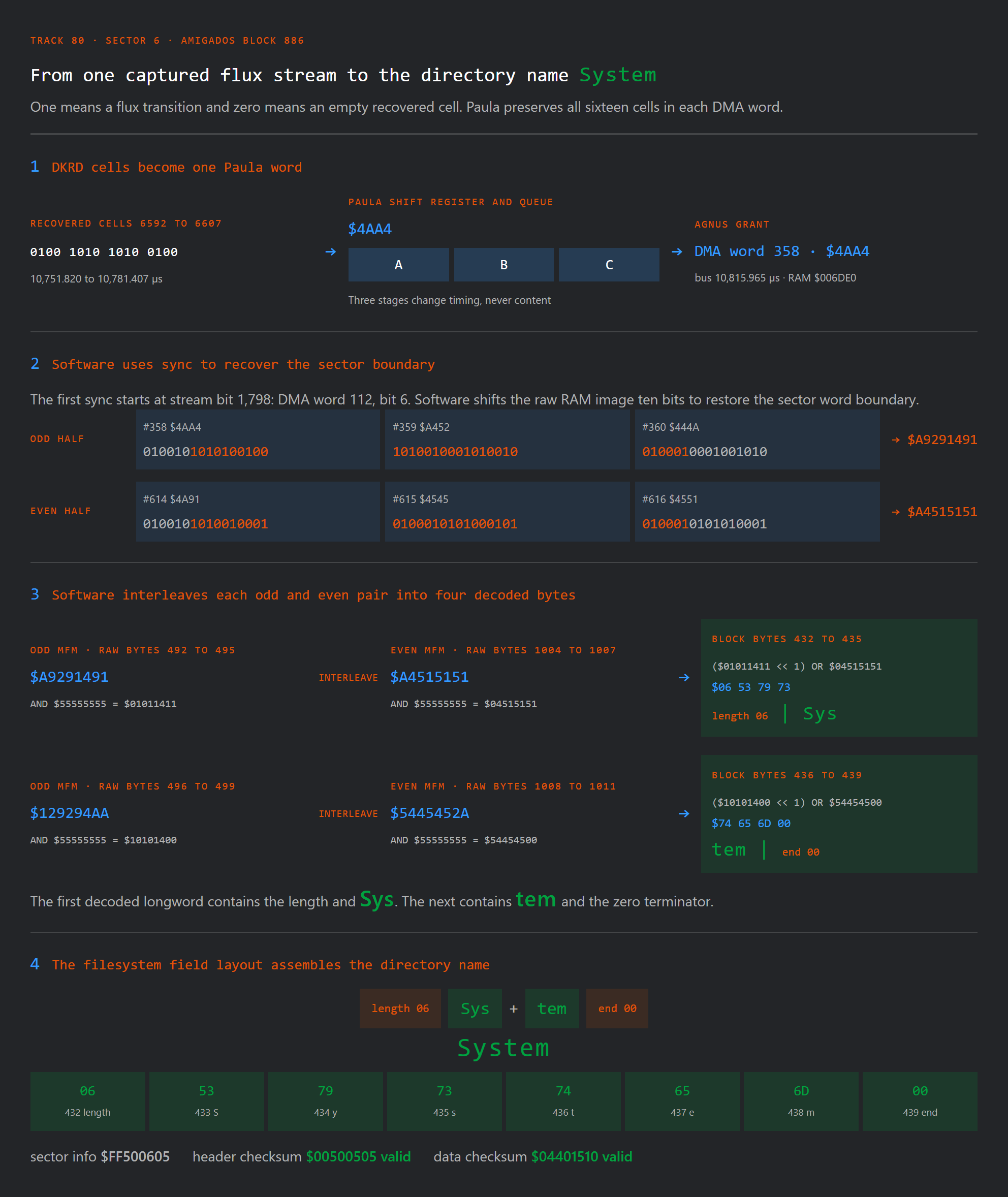
We can now put the complete path together. Figure 7 follows one example from flux transitions entering
Paula, through its raw DMA words and Agnus, to the alignment and decoding explained in Step 16. The
result is a recognizable name inside a valid filesystem block reconstructed from the captured signals.
 width="1984" height="2356"
alt="Four stage diagram tracing recovered DKRD cells through a Paula DMA word and Agnus into RAM, then showing software alignment and odd and even MFM decoding into bytes 06 53 79 73 74 65 6D 00 and the directory name System">
Figure 7. The whole chain, from captured flux to System. Paula and Agnus
preserve the raw MFM cells as DMA words. The Step 16 operations realign and decode them. The filesystem
field then yields a length byte, the six charactersSystem, and the following zero byte.
13 captured sector headers from track 80decoded validation: 11 unique, then 6 and 7 repeatsector block kind name size or result 6 886 directory System 7 887 file header block Insurance.info 622 bytes 8 888 OFS data block (file contents) block 1 of Insurance.info 488 bytes 9 889 OFS data block (file contents) block 2 of Insurance.info 134 bytes 10 890 directory l 0 880 root AutoInstall the volume itself 1 881 free space map which blocks are in use 2 882 file header block DF-Prep 55,740 bytes 3 883 file header block .info 47 bytes 4 884 OFS data block (file contents) .info 47 bytes 5 885 directory c 6 886 directory System second revolution 7 887 file header block Insurance.info the transfer ends inside this repeated block All thirteen header checksums are valid, as are twelve of the thirteen data
checksums. The word count from step 15 runs out inside the final sector, so its data arrives
incomplete. The volume is called
AutoInstall. Track 80 holds its root block, free space map, three directories, three file
header blocks, and three OFS data blocks containing file contents.An incorrect phase, lost cell, changed word, or faulty
odd and even merge would break these checksums or structures. Their agreement validates the
electrical reconstruction end to end.complete file: .infoall 47 bytes of the file contents, recovered from sector 40000 F3 4C 00 12 00 00 16 22 00 00 02 8C 00 00 00 BD .L…..”…….. 0010 49 6E 73 75 72 61 6E 63 65 0A 53 68 65 6C 6C 0A Insurance.Shell. 0020 53 79 73 74 65 6D 0A 44 46 2D 50 72 65 70 0A System.DF-Prep. Now scroll back to the photograph at the top of this post.
c,System,
l,DF-Prep, andInsurance.infoappear in both the recovered
filesystem structures and the Shell listing. Those structures came from DMA words observed on the
captured chip bus. -
STEP18
The same interface starts a second read
Before the Shell finishes printing the listing, the capture also records the setup sequence at the
beginning of the next track read.the second readcaptured repeat setup1 DSKPTH / DSKPTL $0000 / $6B14 reload the same buffer 2 DSKLEN $024 $9CBE first length write 3 DSKLEN $024 $9CBE second write arms the read 4 captured sync pair cell offset 4 a different word phase from the new arming instant The new arming instant places the captured sync pair at cell offset 4 rather than cell offset 6.
The capture ends partway through this second transfer, so this is a phase check from one pair.
What the capture proves
The dir command gave us a real operation to follow. A single interpretation accounted for the flux intervals, the
recovered cells, the word boundaries, the DMA requests, the bus grants, the sync displacement, and
the blitter correction. Applied to the captured words, it produced valid sectors, valid checksums,
and coherent filesystem blocks. The partial second read repeated the setup and placed its captured
sync pair at a different word phase.
Recovering System and DF-Prep from the same captured signals provides the final
human readable check on this account of Paula’s read path.