Validating my dataflyer BUSS PAL replacement GAL
As some of you that have been following my reverse engineering efforts over the last few years, one of the tasks I took on was reverse engineering the BUSS PAL TIBPAL16L8-25 present in on the Expansion Systems Dataflyer plus SCSI-ONLY card. My PAL reverse engineering tutorial series on this site documents some of the steps involved.
Overview
This testing approach begins with capturing logic analyzer data from the original PAL. The recorded data is then processed using Python and Pandas to generate test vector input files. These files are used by a MicroPython script running on a Raspberry Pi Pico to replay the captured inputs to the GAL, allowing for a comparison of its responses against the original PAL, which serves as the reference standard. The Pico outputs test result files that indicate which tests passed or failed, along with basic statistical summaries. Let’s break down each step in more detail.
The Hardware
While the GAL functioned normally when I replaced it, I always wondered if there were edge cases I hadn’t accounted for. Previously, I built a PAL Stimulator for basic testing, and while it worked, I never fully completed the design. Eventually, I repurposed the Teensy from that project for something else.
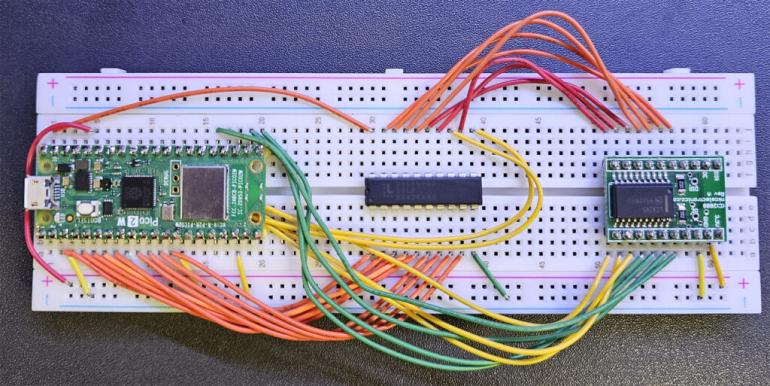
Now, I’ve revived the testing effort with a new version—the PAL Stimulator 2025—this time using a Raspberry Pi Pico 2W. However, unlike the Teensy, the Pico isn’t 5V tolerant, so I had to add a voltage translator to protect its GPIOs from the PAL’s output. This introduced about 15 extra wires, making debugging even more challenging.
On the left is the Pico, the test GAL is in the center, and on the right is the LCX245-based voltage converter board. You might recognize this same board from my earlier project, where I used it to convert 5V video signals from the Amiga for input into an FPGA.
I typically prefer wire-wrapping on solder-based protoboards, but I was out of stock. Wire-wrapping feels more permanent and reliable to me. That said, despite the common claims of unreliability and capacitance issues, solderless boards work just fine for many hobbyist projects. There’s nothing inherently wrong with using them.
Testing Scope
As any good QA engineer will tell you, having a comprehensive test suite is essential to catching as many edge cases as possible. My testing covers the following:
- RESET Line Behavior: This input from the Amiga is asserted during boot, and the card should return to an unconfigured state when this happens.
- ROM Reads: Verifying that, upon boot, the card correctly executes firmware from its onboard ROM.
- Autoconfig Address Assignment & 373 Latch: Ensuring the Amiga correctly relocates the card from its default temporary address space (0xE80000) to a permanent one, typically 0xE90000 on my A500.
- Latched Address Handling: Confirming that the previously latched address is properly pushed to the comparator via the output enable (OE) signal.
- Idle State Testing: Checking behavior during pre-ROM read idle, pre-configuration idle, and post-configuration idle states.
- General Read/Write Operations: Ensuring proper HDD access functionality.
In total, I created around 1,000 tests—and fortunately, every single one has passed!
Initial Capture
A post detailing the logic analyzer configuration, physical dip chip hook up, and all of the associated details could easily be larger than this entire post. But I am planning on putting that together for the reverse engineering PALs series, so stay tuned.
For this post, what’s important to know is that I am capturing, at 100mhz, every important pin on the original PAL in situ. This means that I’m booting my Amiga with the SCSI card in place, and then watching all of the inputs, and all of the outputs from the PAL. I perform reboots, reads, and writes, and then capture how the PAL reacts to the inputs from the Amiga. For this particular PAL, there are (11) input signals, and (7) output signals. I call these input and output WORDS, which are just a binary concatenations of each pin. Pin 1 is the MSB of the input word, Pin 12 is the MSB of the output word.
Below is the raw CSV output from the logic analyzer. Each row is one sample in time. It represents a 10ns (1/100mhz as a period) view of all of the pins in question. Each pin is either a 0 or a 1.
And then the associated output pins

Post-processing Logic Analyzer Captures
A few different things have to be done to process this raw capture data from the logic analyzer. First, due to the propagation delay (about 25ns for most operations), of the original PAL, the output of the PAL will appear shifted down in time (ie later) in the .csv’s. I handle this by deleting the first couple output rows, and then shifting the entire dataset up. Next, I form the input and output words, ensure stability of the data (because the input could be changing rapidly, or the output changing as a result of the input), and then remove unstable readings and consecutive duplicates.
df[output_pins] = df[output_pins].shift(-2) # Shift outputs up by 2 rows
df = df.iloc[:-2] # Remove last 2 rows to keep DataFrame aligned

# Convert inputs/outputs to integer values
df[input_pins] = df[input_pins].astype(int)
df[output_pins] = df[output_pins].astype(int)

# Convert bit sequences into integer words
df['InputWord'] = df[input_pins].apply(lambda row: ''.join(row.astype(str)), axis=1).apply(lambda x: int(x, 2))
df['OutputWord'] = df[output_pins].apply(lambda row: ''.join(row.astype(str)), axis=1).apply(lambda x: int(x, 2))

# ---- **New Filtering Logic (Rolling Stability Check)**
df['InputStable'] = df['InputWord'].rolling(3, min_periods=3).apply(lambda x: (x[0] == x[1] == x[2]) * 1, raw=True).fillna(0).astype(bool)
df['OutputStable'] = df['OutputWord'].rolling(3, min_periods=3).apply(lambda x: (x[0] == x[1] == x[2]) * 1, raw=True).fillna(0).astype(bool)

# Keep only rows where both Input and Output are stable for three consecutive readings
df = df[df['InputStable'] & df['OutputStable']].drop(columns=['InputStable', 'OutputStable'])

# ---- **Remove Consecutive Duplicates**
df = df[df.drop(columns=['Time']).ne(df.drop(columns=['Time']).shift()).any(axis=1)]
Then, just using Excel, I export a simple two column csv which includes the input word, and expected output word. This forms the test vector input files for the pico replay stimulator.
Replaying those test vector files on the Pico using micropython
from machine import Pin
import utime

# Define input and output pins (matching PAL/GAL)
INPUT_PINS = [Pin(i, Pin.OUT) for i in [1, 2, 3, 4, 5, 6, 7, 8, 9, 11, 13]]  # 11-bit input
OUTPUT_PINS = [Pin(i, Pin.IN, Pin.PULL_DOWN) for i in [12, 14, 15, 16, 17, 18, 19]]  # 7-bit output

def write_input(value):
    """Set input pins based on an 11-bit decimal value."""
    value &= 0x7FF  # Mask to ensure only 11 bits are used
    for i, pin in enumerate(INPUT_PINS):
        pin.value((value >> (len(INPUT_PINS) - 1 - i)) & 1)

def read_output():
    """Read the PAL output in MSB-first order and ensure 7-bit range."""
    output_value = sum(pin.value() << (len(OUTPUT_PINS) - 1 - i) for i, pin in enumerate(OUTPUT_PINS))
    return output_value & 0x7F  # Ensure max value is 127 (7-bit)

def process_test_vectors(input_filename, output_filename):
    """Reads test vectors line-by-line, executes tests, and writes results efficiently."""
    total_tests = 0
    passed_tests = 0

    try:
        with open(input_filename, 'r') as infile, open(output_filename, 'w') as outfile:
            for line in infile:
                line = line.strip()
                if not line or line.startswith("#"):  # Ignore empty lines and comments
                    continue

                parts = line.split(',')
                if len(parts) != 2:
                    continue  # Skip malformed lines

                try:
                    input_value = int(parts[0].strip())  # Read input as decimal
                    expected_output = int(parts[1].strip())  # Read expected output as decimal
                except ValueError:
                    continue  # Skip lines with invalid numbers

                # Apply input to the PAL and read output
                write_input(input_value)
                utime.sleep_us(10)  # Short delay for stabilization
                actual_output = read_output()

                # Ensure binary formatting matches test vector expectations
                input_binary = "".join(str((input_value >> (len(INPUT_PINS) - 1 - i)) & 1) for i in range(len(INPUT_PINS)))
                expected_binary = "".join(str((expected_output >> (len(OUTPUT_PINS) - 1 - i)) & 1) for i in range(len(OUTPUT_PINS)))
                actual_binary = "".join(str((actual_output >> (len(OUTPUT_PINS) - 1 - i)) & 1) for i in range(len(OUTPUT_PINS)))

                # Check pass/fail and write results incrementally
                if actual_output == expected_output:
                    outfile.write(f"{input_value}, {actual_output}, PASS\n")
                    passed_tests += 1
                else:
                    outfile.write(f"{input_value}, {actual_output}, FAIL\n")
                    outfile.write(f"EXPECTED {expected_output} ({expected_binary}) but got {actual_output} ({actual_binary})\n")

                total_tests += 1

            # Append summary statistics
            outfile.write(f"\n{passed_tests} out of {total_tests} tests passed.\n")
            outfile.write(f"{total_tests - passed_tests} tests failed.\n")

        print(f"Test results saved to {output_filename}")

    except OSError:
        print(f"Error: Unable to access {input_filename} or {output_filename}")

# Run test from file
process_test_vectors('test_vectors2.txt', 'test_results2.txt')
Test Results
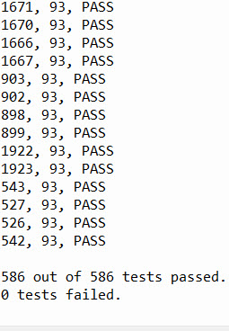
The test results are very boring, which I can’t say I’m mad about. I have two sets of test vectors, combined to over 1000 tests.
Summary
Over the past few years, I’ve been working on reverse engineering the BUSS PAL (TIBPAL16L8-25) from the Expansion Systems Dataflyer Plus SCSI-ONLY card. My PAL reverse engineering tutorial series documents much of this process.
To validate my findings, I needed a way to systematically compare the behavior of the original PAL with a replacement GAL. To do this, I built a PAL testing framework that captures real-time PAL transactions, processes them, and replays them to a GAL, allowing for direct comparison. The testing system is powered by a Raspberry Pi Pico 2W running MicroPython, which interacts with the PAL and GAL to automate testing and record results.
The process began by capturing high-speed signal data from the PAL in a real Amiga system, logging how it responds to various inputs over time. This raw data was then cleaned up and structured into test vectors using Python and Pandas. These test vectors were fed into the Pico, which systematically replayed them to the GAL while recording the output for verification. A voltage level translator was required to protect the Pico from the 5V signals coming from the PAL, adding some annoying complexity to the hardware setup.
With this system in place, I was able to run extensive automated tests covering different operational scenarios. The results confirmed that the GAL correctly replicates the behavior of the original PAL, with every test passing successfully. This approach not only validated the GAL replacement but also provided a structured method for future reverse engineering of similar logic devices.
Stay tuned for more details in my PAL reverse engineering series, where I’ll dive deeper into the process and tools involved!


