Building the ReAmiga from scratch. Part5 Final part!
ok this part is more about the extras etc.
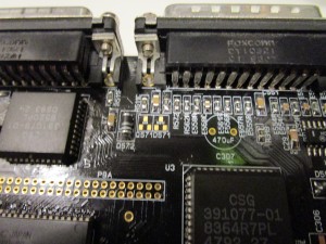
First we have some weird A1200 “extras”. as you might have noticed I missed one transistor and one diode at the parallelport:
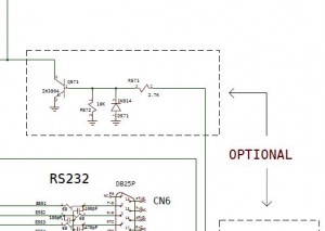
Looking at schematics
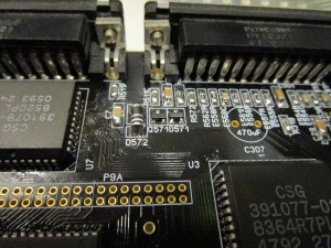
this is “optional” seems to be connected to the audio in. I might remove this in the future. but for this card. I will populate it:
And then at the PCMCIA port:
Lets take a look at the shcematic again:
oh part of the nonsupported flash option. so. THIS can sure be skipped. Will be removed in future.
now all “normal” A1200 stuff is done. Lets talk about “extras” and lets begin with the Composite/S-Video:
First of all before talking about the AD724 I have populated above the IDE Connector.
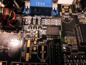
you can see 3 0ohm resistors that selects either PAL or NTSC. this is configured for PAL.
the Bottom resistor R63 tells alice what mode to start in as default. the other 2 is for the composite chip and timing.
so you MIGHT want to put a jumper or so on R63 if you want to be able to switch between PAL and NTSC screenmode.
(this however does NOT affect the PAL or NTSC Osciallator you have installed, the 28MHz one)
Well the AD724 is the chip doing the composite and Svideo. instead of the obselete CXA chip on the A1200.
Now you need to populate the trimmable CAP. (THIS you can skip if you are using NTSC mode on the 2 top 0ohm resistors)
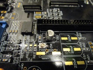
Here it is installed. AND I also installed the 22uF electrolyte.. (that cap is needed even for NTSC but not the trimable one)
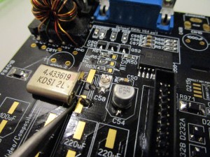
and the oscillator. you can either take one off the A1200 board or add a new surfacemounted version. I have one from an old A1200 board:
(this can ALSO be skipped in NTSC config)
make sure the oscillator does not short with the SMD pads opinted out here on picture.
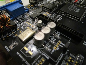
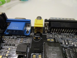
Now add the 220uF (huge) caps and composite connector. and you are done. the trim cap needs to be adjusted.
here there have been reports of issues. it seems that SOME trimcaps works better than others. will investigate in this.
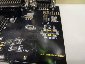
Now time for the NMI (IRQ7)
This is a handy tool for coders as some assemblers (asmpro etc) can enable a IRQ7 function that makes it possible to break eternal loops etc.
also software for “freezing” similiar to the Final Cartridge on the 64:
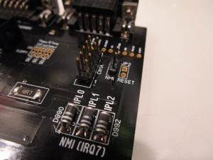
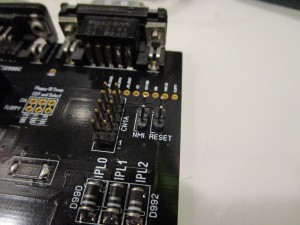
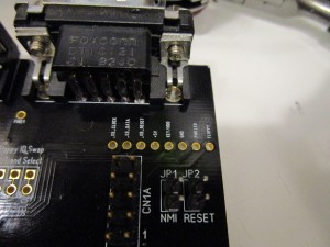
Add 3 diodes and the switch header:
When you short NMI you trigger a IRQ7.. if no software handling IRQ7 is installed. you will notice that the machine just will pause when the button is pressed.
And when we are at it: add a Reset header
Shorting this and the machine will simply just reset.
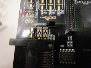
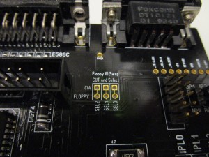
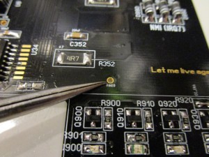
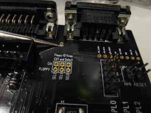
Now we have the Floppy SEL pad:
Usually you do not do anything here. but if you do want to have the possability of swapping DF0 and DF1. like having a gotek externally but want it to be df0 and the internal drive will be a df1. you can cut the trace between the holes and make a switch that swaps the positions of the SEL signal. more or less like: DIY Boot Selector
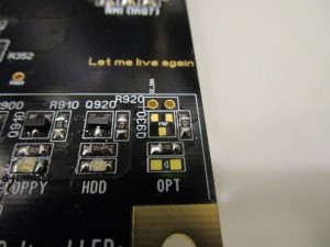
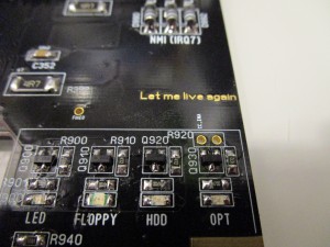
ok LED. “optional”
this is a special led. it is not really connected anywehere. you can see a header at the top. this is input and output. the right hole is the input to the led. technically you can put in a led here and solder a wire to the right pad and to anywhere you want to trigger the led.
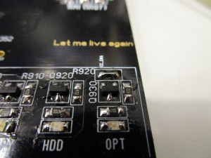
Here I installed the led and PNP transistor. most people I guess want this to be connected to PCMCIA activity. and that is actually the left hole. so by bridging those holes. “OPT” gets to be PCMCIA activityled:
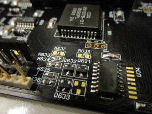
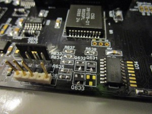
BUT first you will need to add 2 resistors close to the floppy powerconnector:
R637 should be a 10K and R638 should be a 4.7K:
Now it is done. if you populate the empty location with a PNP transistor. that signal will also be present at the hole for the led board that is not connected here. (like on all A1200 actually)
Then we have the A500 keyboard connector:
but I MUST confess. I have never really tried this ![]()
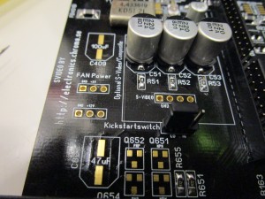
This is “fire” button of port 0 and 1. I did put them here to be able to access those signals if you want to do a automatical kickstart switch or so based on those.
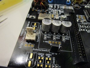
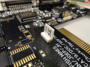
We also have FAN power:
Here I populated the 5V port with a PC style fan connector. 5V to let the fan run more quiet. (some fans does not work at 5V)
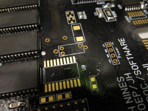
and to end with we have the extra powerconnector:
This can be used to get power to something you need. OR ADD extra power to the PCB if you have a BPPC+BVision where it is recomended to add extra power close to the CPU connector. (also in the manual for the BPPC/BVision)
All done.. put all electrolytes in place. ready for ultrasonic:
Proms with Kickstart 3.1 and Kickstart 3.1.4.
