Building Amiga 4000T (Part 2, Motherboard)
OK. You have the daughterboards done. this is quite essential as it helps the building process.
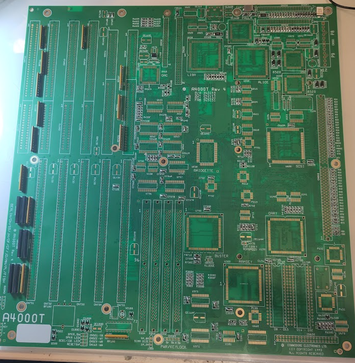
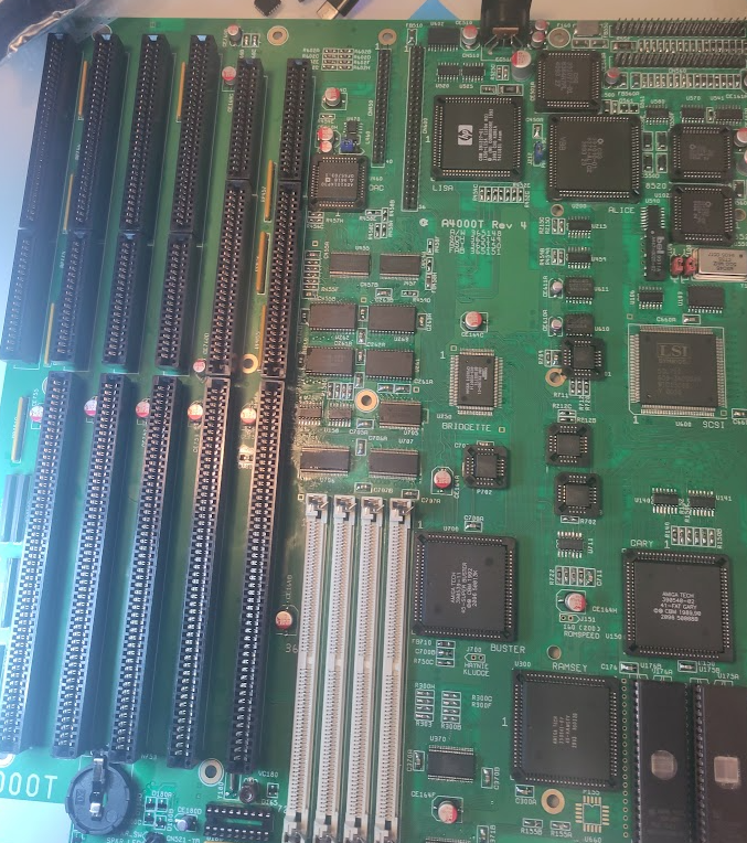
the A4000T is a “weird” solution with several DBs and if you ask me. feels very “hacky” you get a feeling Commodore was in a hurry doing this. It DOES fit in a standard AT Case. I guess that is a “improvement” from the 3000T. Anyways lets start building. This differs some from other amigas.
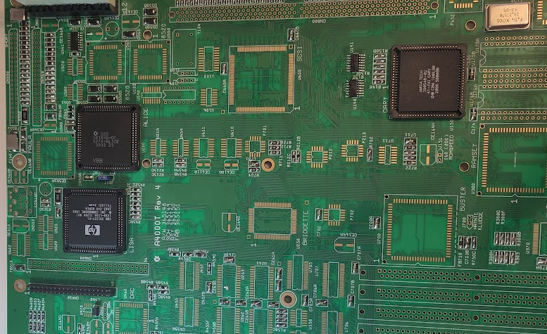
I Start with a board with all passives on as usual (except electrolytes)
As always. GAL chips needs to be programmed files at: https://www.amigawiki.org/doku.php?id=en:parts:pld_download
So lets start with POWER:
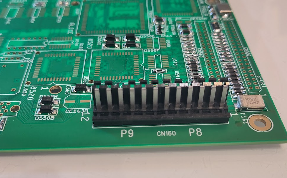
you MIGHT need to shorten the pins of the powerconnector. for me this worked fine however.
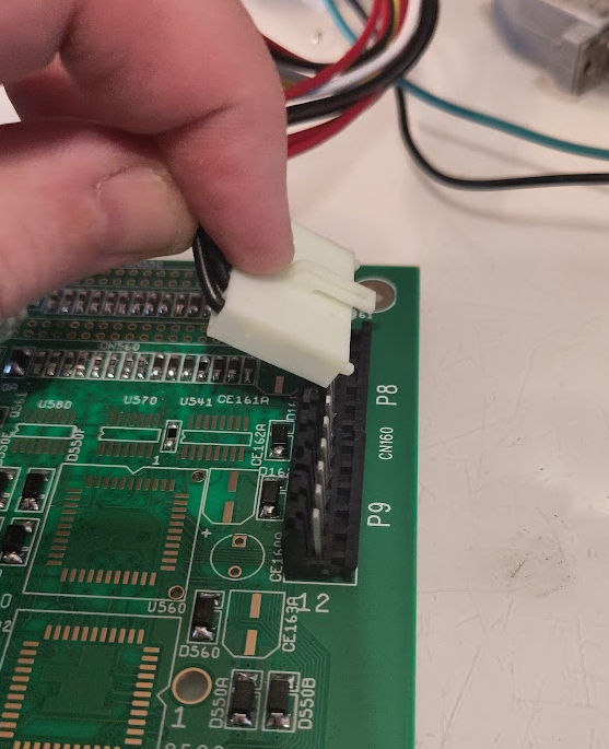
I tilt the connector like this to insert the powerconnectors. there are 2 of them on AT PSUs.
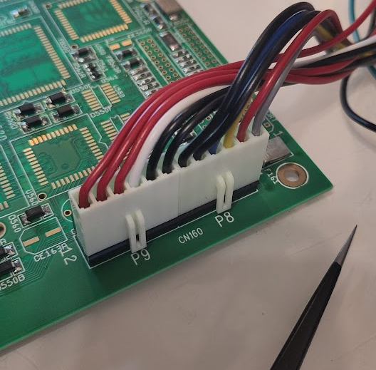
Rule to remember is “Black to the middle”, do NOT do this wrong as some AT PSUs does not have short protection. smoke might appear.
During assembly I put a temporary led for the powerled as this is important:
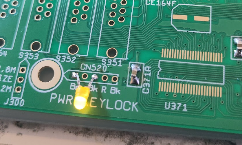
so lights on at power on! good.
So next step is to get the Reset working:
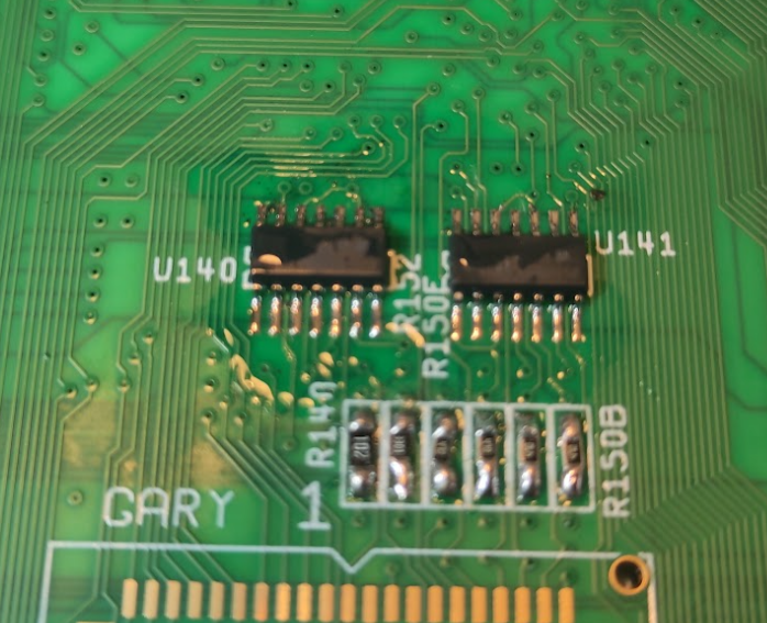
Add U140 (74F32) and U141 (7407)
Then it is time for next part:
IMPORTANT note about PLCC sockets:
This is by far the most common reason to people having problems with their builds.
it is NOT easy to do a good proper PLCC socket solder.
how I do it is to NOT remove the inner frame! it is a important part of stability.
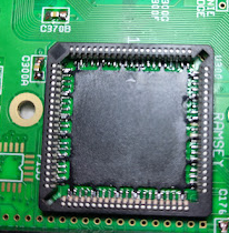
I solder pin by pin under microscope. also the chips you use. if you are using removed chips they need to be cleaned from old solder and flux or socket will get damaged and not working.
IF you build using sockets and have issues. I would say the sockets are most likely the reason.
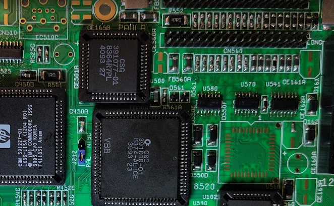
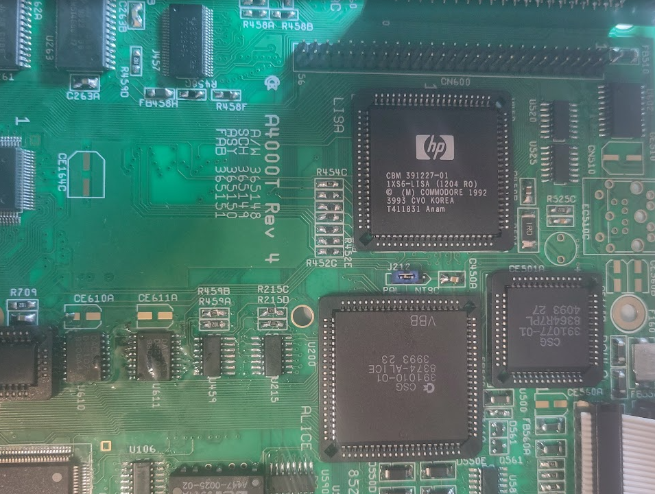
You add LISA, ALICE, FAT GARY
U541 (74HCT166)
Y154 (28MHz)
PAL/NTSC Jumper (Set to wanted startup mode)
CN450
Now when powering on, you should get a V and H sync.
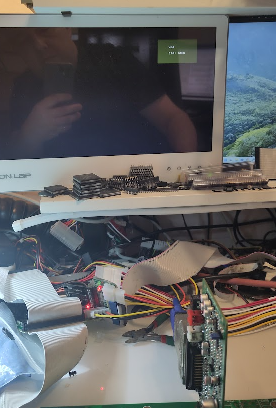
my monitor notices it here by going out of powersave mode and give a VGA splash screen. how it behaves for your setup, I do not know.
Next step is to get he CPU Clock working:
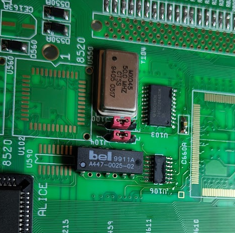
Put in J104, J100 and jumper correct, on photo you see INT.
this is typical for 030 card, Cyberstorm MK2, BFG9060.
set to EXT for 3640, Cyberstorm MK3, TF4060 etc.
check your cpu card manual for correct setting. (Some cyberstorms is dependent of cpu and clock etc)
U103 (74FCT244)
U106 (74F74)
50MHz Oscillator
U102 Delayline.
To get correct IRQ Handling
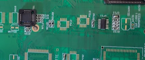
we add U711 (74F86)
and P701 (16V8)
Now it is time to make it run code.
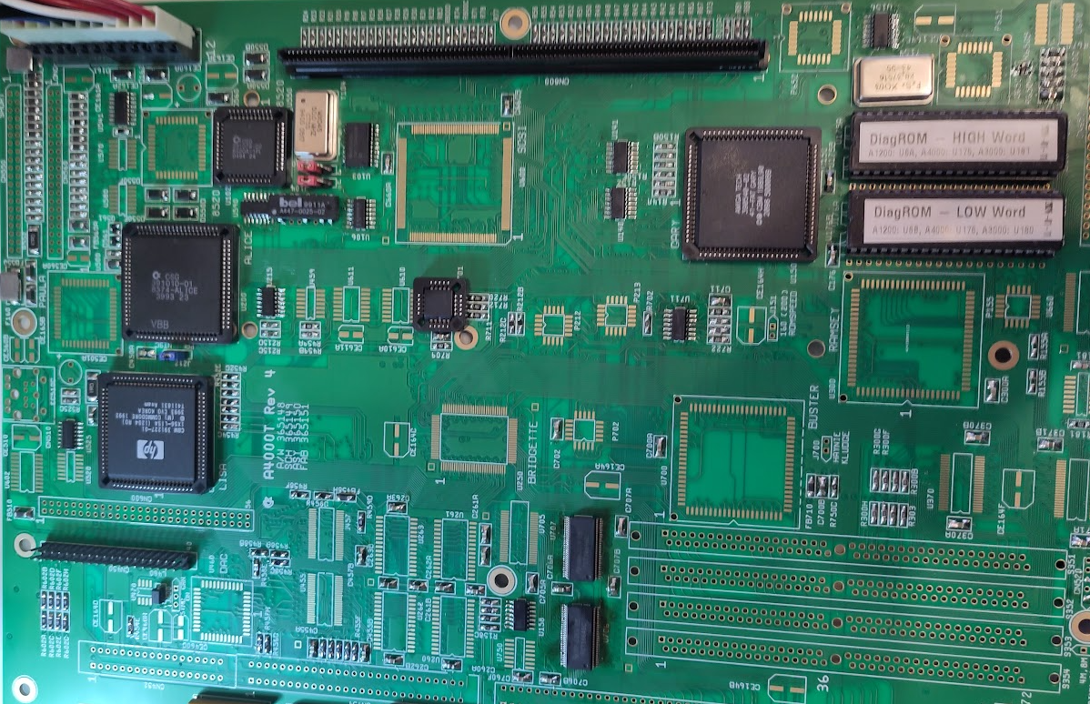
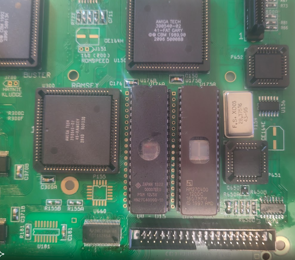
First ROM sockets:
the 4000T handles 2 types of roms. 27C400 is the most used . so you use the holes one step to right as you can see here.
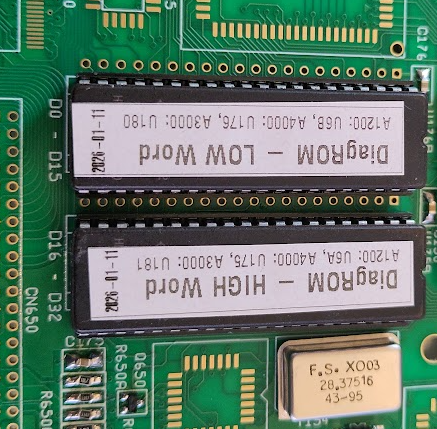
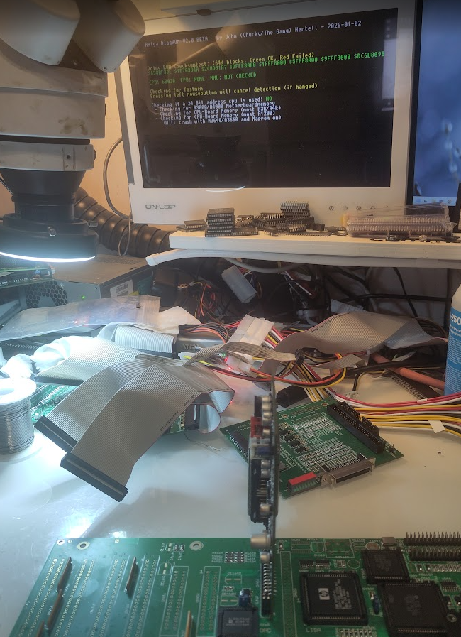
And add DiagROM. you can see here how to solder and orientation.
now add:
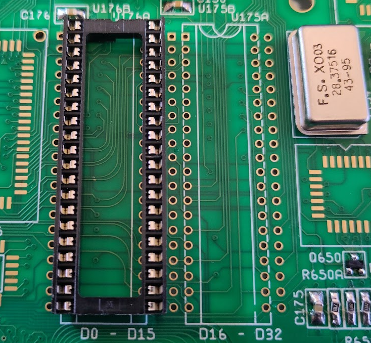
CPU Slot.
U550 (8520)
U590 (74HCT174)
U525 (7407)
U156 (74F00)
U215 (74F04)
U158 (74F08)
U706, U707 (16646)
U705 (16245)
(On picture U705 is not populated it should be on. took photo at wrong phase)
If you power on now. powerled will flicker some. atleast go to a brighter light after aprox 1 sec.
Now time to get some serial data out. and here you have a big difference to other builds.
you NEED Buster.
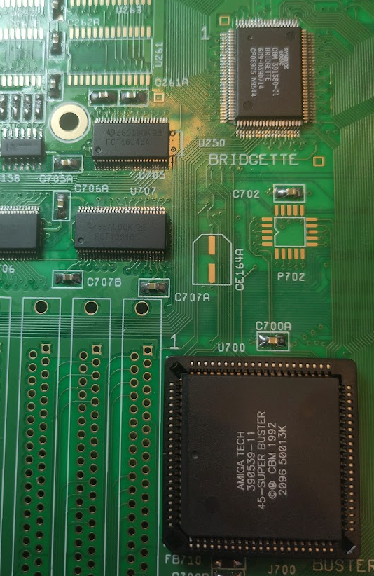
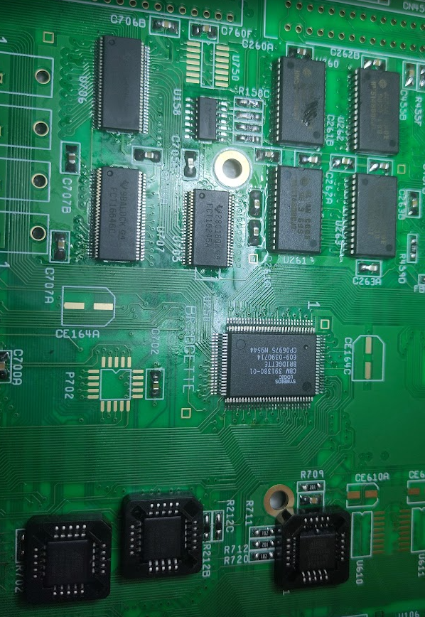
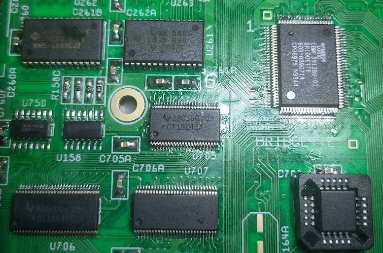
Solder in Buster, Bridgette
Also add Paula
U570 (1488)
U580 (1489)
U520 (74HC4066)
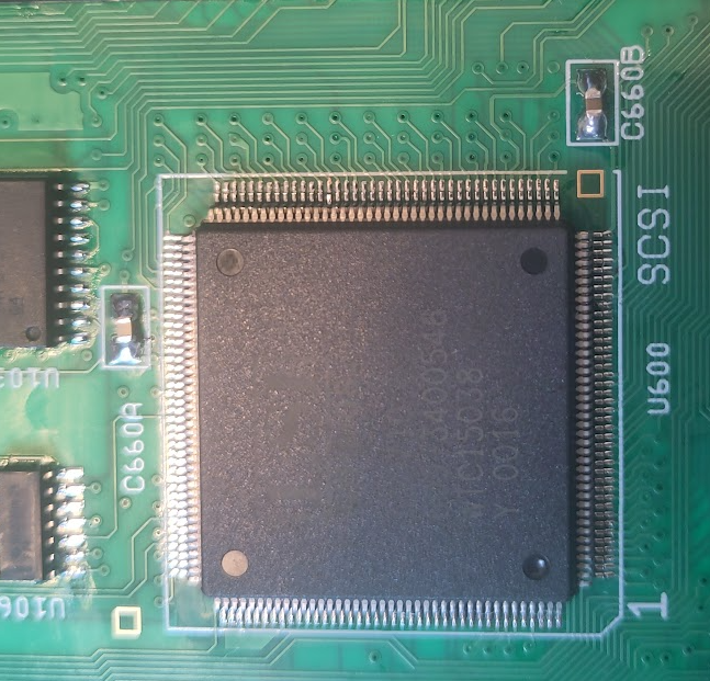
and SCSI Chip, U600 (MIGHT not be needed at this part. but I did have some weird issues that soldering in this seems to solve)
NOW Connect the port DB:
Remember short to SHORT etc.
Connecting those wrong MIGHT damage Paula/CIAs
Now you can connect serialcable to your PC and see DiagROM serial data out.
Time to add some Chipmem:
Add P212, P213. and Chipmem:
U260-U263

This shows how it looks like with one chip soldered in with DiagROM V2.0
Anyway with all 2MB Chipmem soldered in and working. Time to get something on the screen.
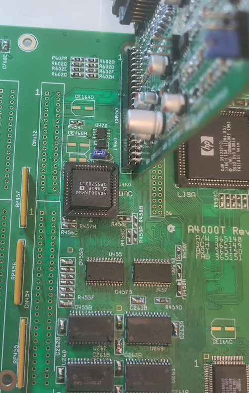
Solder on U455, U457 (16245)
U459 (74F74)
U470 (LM385)
U460 (ADV101)
J500 And put on SYNC.
and you should get a picture:
Next just add the next CIA to get Paralell port working and all CIA tests in DiagROM:
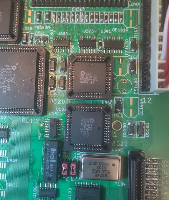
BE WARNED! notice that the 2 8520 chips have DIFFERENT rotations!!
OK Fastmem next. yet another warning. there are 2 different types of SIMM sockets. both works but how what direction you use differs. so put a simm into it and look where the notch (pin 1) is located:
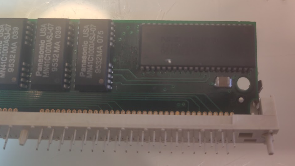
You see the pin here. this is to be put at “pin 1”
Like this:
so put all sockets to this direction. make sure pin 1 is towards the back of the board. (to keyboard connector)
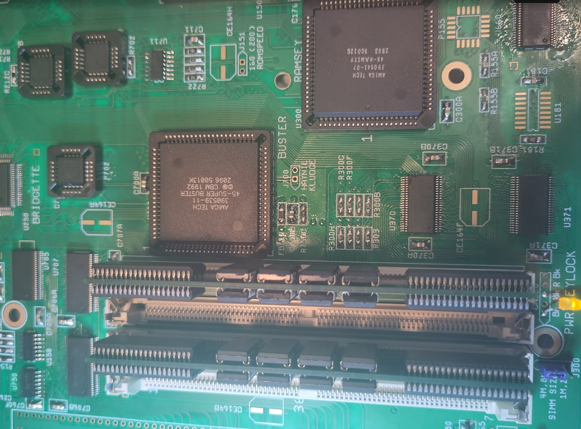
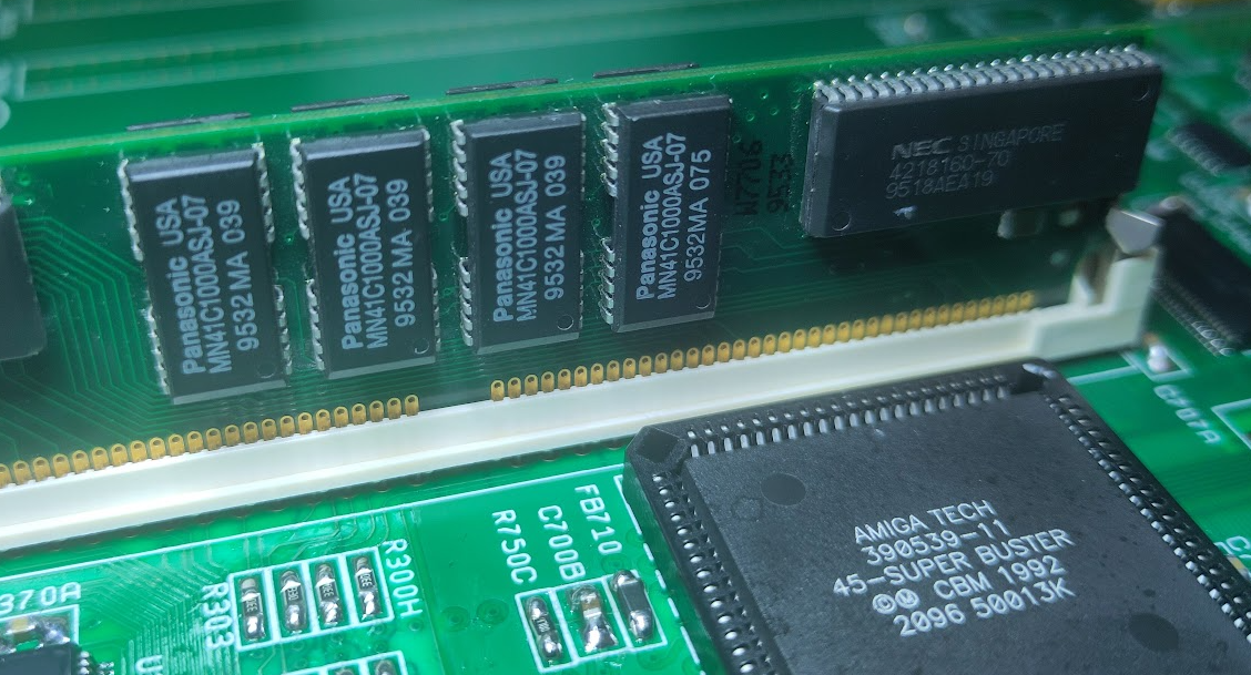
So you add Ramsey.
U370, U371 (16245)
Simm sockets.
J300 and set to correct mem size.
here you can see I added 2 8MB simms giving me 16MB Fast. (16 IS still max!)
you can use 4 4MB simms aswell.
Get some Zorro stuff to work:
Add U750 (74HCT32)
P702
Time for IDE:
Add
U670 (74HCT174)
U660 (16245)
P651
P652
IDE Connector.
and next finish the SCSI:
By adding:
U610, U611 (Termination ICs)
U602 (74F244)
and Connector to CN600.
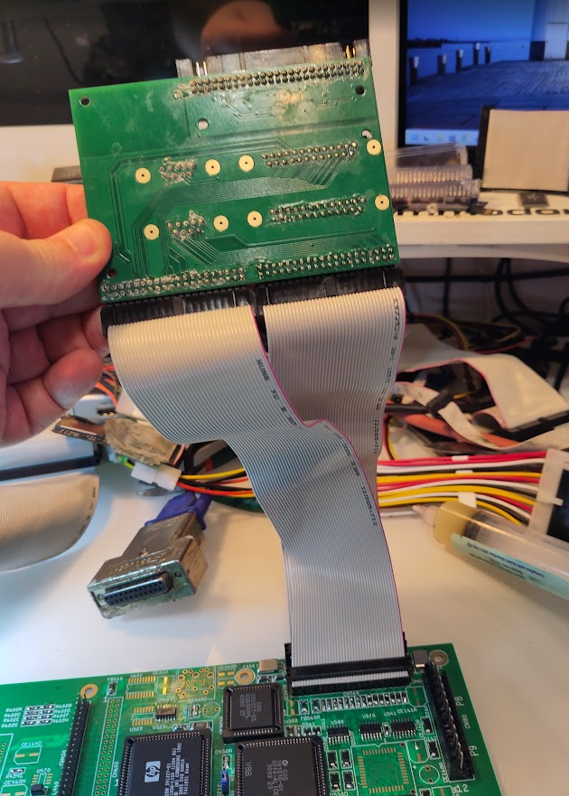
A talk about SCSI termination on the 4000T:
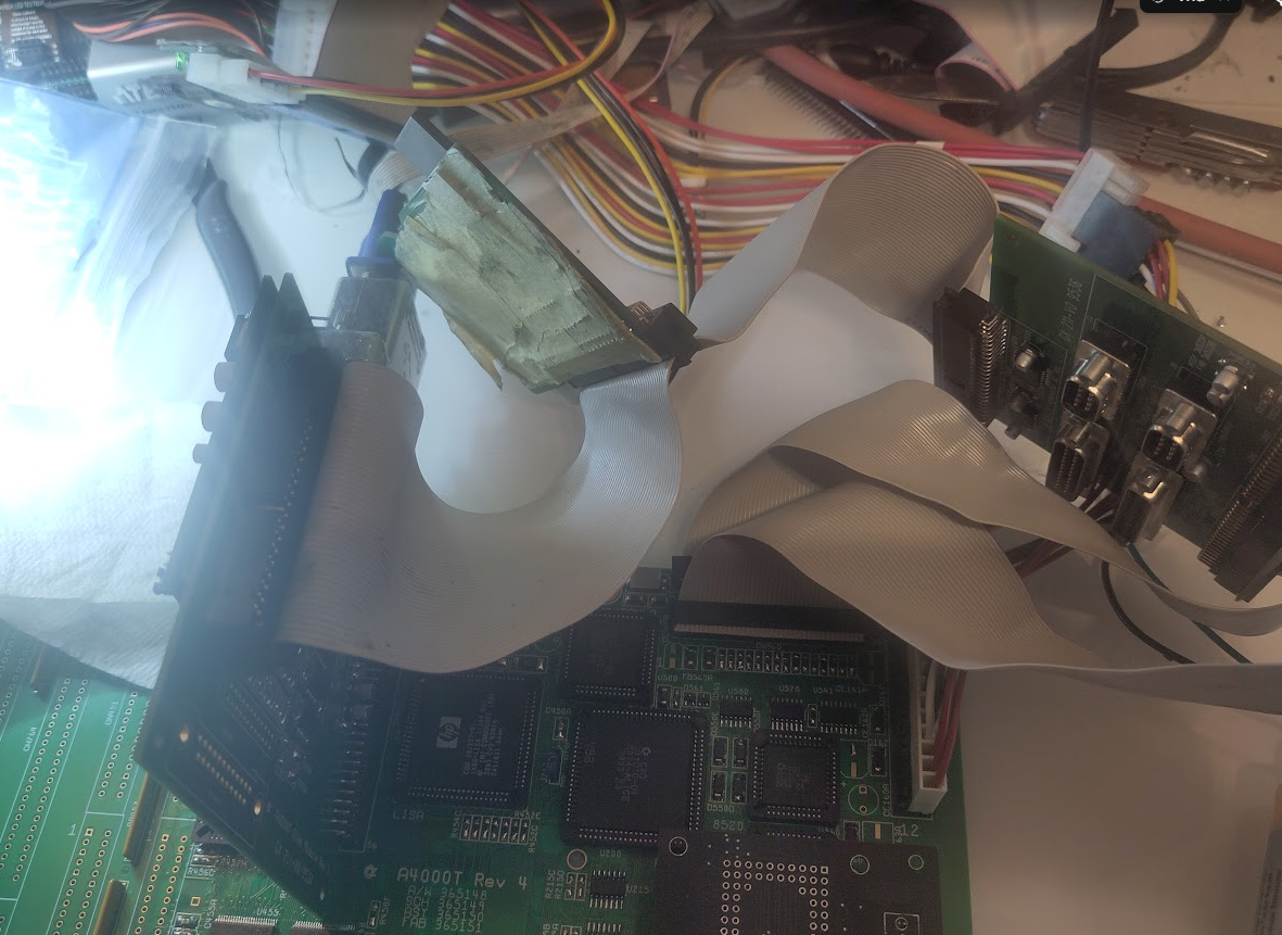
You might remember that the port DB have a terminator on it. so in this messy photo you can see my SCSI cable going from the SCSI DB. to my SCSI2SD and then to terminator of the port DB.
this is how it “Should” be connected. having wrong SCSI termination can corrupt disks, it can cause instabilty etc. SCSI is messy! REALLY messy! it was good “back in the days” but now it is a reason of MUCH headaches. theory is “simple” first and last device should be terminated . nothing else!
NOW you can add Kickstart and boot:
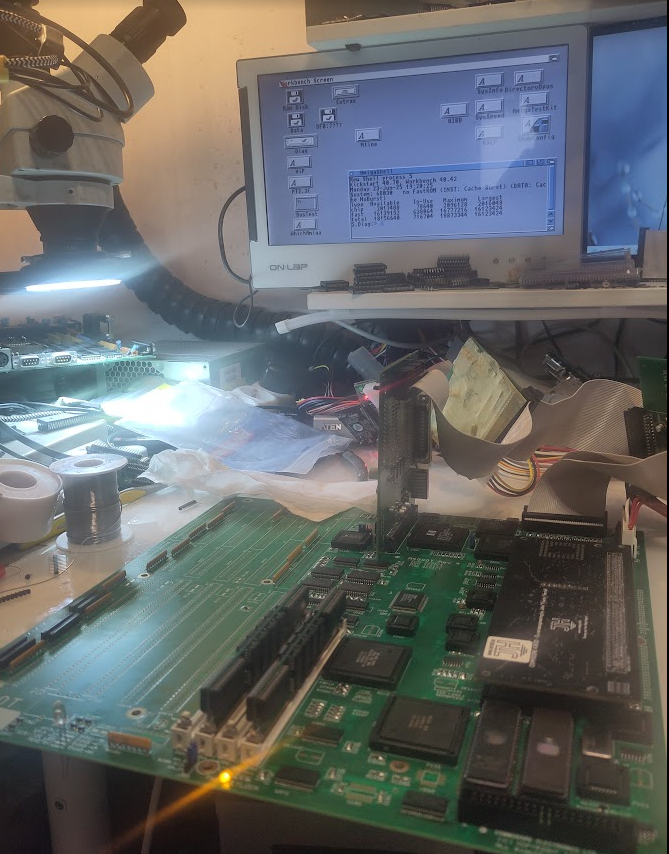
REMEMBER this uses the 4000T rom. you CAN use 4000D rom but then you will loose SCSI.
and as SCSI driver was too large, commodore removed workbench.library from the 40.70 kickstart so you will need to add it. how? look at the internetz. if not. you will not get any icons on screen!
now some finalize stuff like RTC:
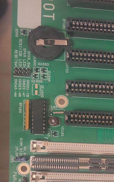
Add
U181 (74HCT174)
3KHz Oscillator
U180 (RTC Chip)
Trim-Cap
Batteryholder
and to end it all remove the temporary led., add header there. add headers for leds, speaker.
Keyboard connector, Zorro / ISA Slots.
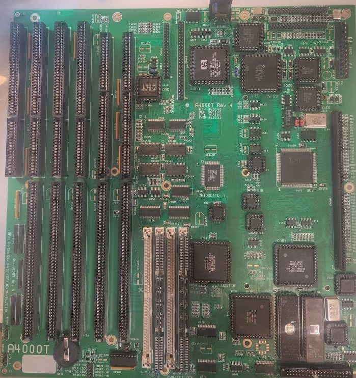
now Clean up flux. ultrasonic if you can etc etc.
and when dried up. add electrolytics:
And you are good to go!.
Oh sidenote. the “ATX DB” style I talked about this is how it looks like:
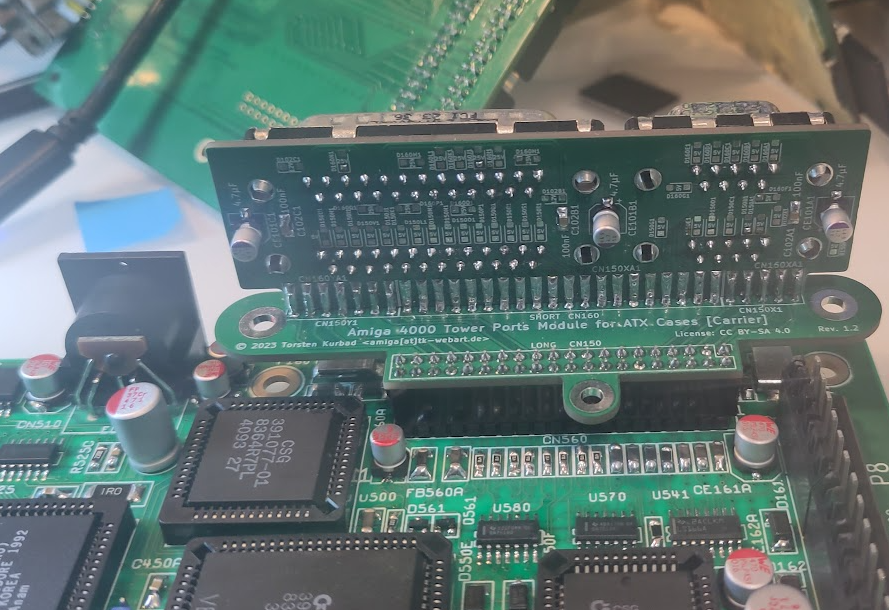
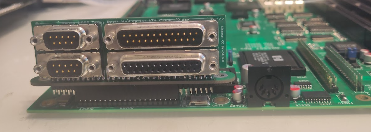
but how well it sits in ATX case etc. NO idea! but good to know. I use this on my bench as my board is loose and used for TF4060 testings etc. so not needing those ribboncables are really nice.