Building the TerribleFire TF530 accelerator board, part 4: Software and Installation
Handling ~40GB of downloaded installation archives is not for the squeamish. And I built the M68000 CPU socket connector. And then there comes the moment of truth.
Disclaimer: This is not an instruction. Use at your own risk. No responsibility taken for whatever you do. Safety first. Kids, dont try this at home.
 |
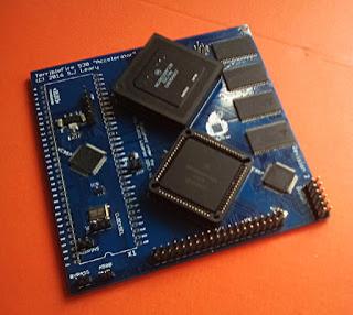
| That's what she looks after cleaning. |
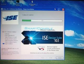
Now that I have a complete TF530, it's time to upload the firmware to the Xilinx CPLDs. Wow, Xilinx really offers a lot of software for download. (And US export regulations are weird.) Picking an older, smaller (3.5GB) version of Xilinx ISE for Linux from their website didn't work out, does not recognize my Diligent-based "Xilinx Platform Cable USB" JTAG interface. Trying Windows version, no success.
 |
| Nope, this one wouldn't do the job. Need more software. |
Next Linux version (8.0GB) didn't work, too. Trying Windows version, no success. I've downloaded about 25GB so far... Well, long story short: A few days and a few more versions later, namely 14.6, there's a new button in Xilinx ISE's GUI: Diligent USB device. Yay. Finally. Job done, nerves wrecked.
Connecting the JTAG cable, and uploading the firmware then worked flawlessly.
Plug it in!
I'll be installing the TF530 into an Amiga 500. The TF530 has to be connected to the M68000 CPU socket on the mainboard. My first thoughts were to build something using wires, but that would leave the TF530 floating around the Amiga's casing, requiring some support. So I decided to go with the "68000 Relocator" board and build some connector from standard 2.54mm-grid pin headers soldered to it. The CPU socket on the mainboard is pretty flat, and it turns out that when using these pin headers you have to solder them to the "68000 Relocator" just at the tip, lifting up the board from the CPU socket as far as possible. And of course we don't want to damage the CPU socket by inserting wide pins into the very narrow CPU-pin slots, so the pin headers need some filing! Only next time I will do the filing before soldering the TF530 to the Relocator board, saves a lot of cleaning... But I'm quite pleased with the results, and it looks as if I can still - should I ever need to do so - put the M68000 CPU back into the socket and it's pins will make proper contact.
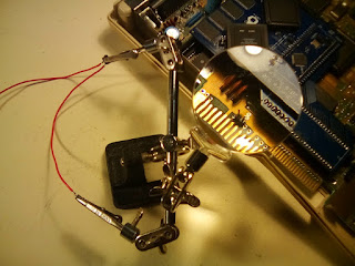
Final step of installation is to connect the TF530's "A500" header to the Amiga 500's expansion port. "OVR" to pin 17, and "INT2" to pin 19. A small 2-pin header can (and probably should) be installed there, to be able to unplug the TF530 and the wires. I created it from two individual pins, because the distance between the soldering points on the mainboard is less than 2.54mm. Now that we have pin headers on both ends, a connector cable with two individual plugs on one end and a 2-pin-plug on the other, will certainly come in handy.
 |
| The INT2/OVR header, and building the connector cable. |
What's left to do? Nothing!
Turn it on!
I have to admit this is quite a moment. I started this journey about nine months ago. This is the moment of truth. I'll have a bottle of cold beer ready to go. With a display and the PSU connected, I'm powering up the Amiga...
 |
| The TF530 fully installed. Will it work? |
And...
...nothing. Black screen. No floppy clicks.
Maybe we should install some jumper at "CLOCKSEL".
Let's try again.
And...
Next time we'll see how she really does - watch out for part 5 of our series "Building the TerribleFire TF530 accelerator board"!
Overview and back catalogue of the series:
http://amigaalive.blogspot.de/p/hardware-building-terribefire-tf530.html
